
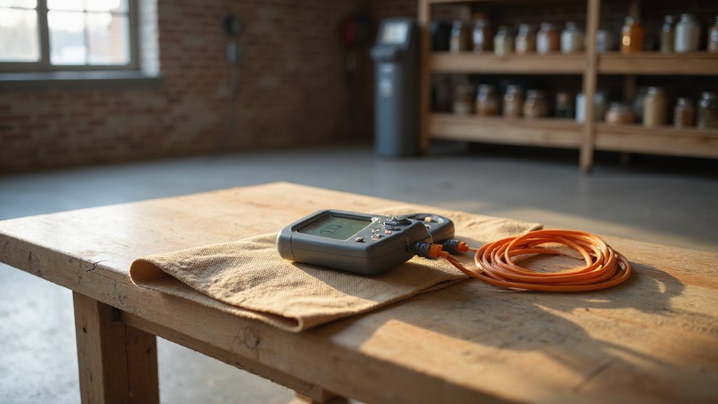

Ever wondered how to safely measure current in a wire with a clamp meter? It’s simpler than you might think — just set the dial to AC or DC current, open the jaws, and clamp around a single wire without touching both live and neutral.
By following a few easy steps, you’ll be able to get accurate readings and troubleshoot your electrical system with confidence.
The full guide below walks you through everything you need to know.
What Is a Clamp Meter and How Does It Measure Current?
A clamp meter measures current without breaking the circuit by using magnetic detection. When you clamp the hinged jaws around a single wire, they function as a ferromagnetic core. This core concentrates the alternating magnetic field generated by the current passing through the wire. The magnetic field induces a signal in a secondary winding within the clamp, based on the transformer principle. The meter then uses its internal turns ratio to convert this induced signal into a direct reading of amperage. Because it detects the magnetic field, you don’t need to disconnect or make contact with bare conductors. To achieve accurate measurements, position the wire centrally within the jaws and ensure only one conductor passes through. Many clamp meters also include additional functions, such as measuring voltage and resistance, making them versatile tools for electrical troubleshooting. For system-level comparisons, this non-contact method is similar to how central inverter designs aggregate current data from multiple strings. For users seeking a reliable clamp meter with a strong build, reviewing options like top battery picks can help ensure quality and performance in related tasks. This tool is especially useful for identifying overloaded circuits that cause your breaker box to keep tripping.
Safety Checks Before Clamping Your Meter
Performing a safety check before clamping your meter is essential. Start by inspecting the meter’s case for cracks or missing plastic; an open or damaged case can compromise safety and accuracy. Examine the clamp jaws for damage, rust, or abnormal gaps that could affect contact or cause erratic readings. Confirm that the flexible sensor insulation remains intact, preventing accidental contact with live parts. Check the test leads for cracked insulation or exposed metal, and verify the continuity of the probes to ensure proper function. Match the meter’s category rating to your circuit’s environment—using a higher CAT rating provides added safety in higher-voltage conditions. Always verify the voltage and current limits to prevent overloading. Ensure the low-battery indicator is off, and replace weak batteries immediately to prevent false readings. Wear appropriate personal protective equipment, keep your hands behind safety guards, and avoid measurements in wet conditions. Listen for any unusual ambient noise that might signal unstable readings, and confirm that recent calibration procedures have been followed. Unlike gel batteries, which require specific charging profiles to avoid damage, never operate the meter with the battery compartment open to avoid accidental contact with internal components. Just as with a solar inverter, being mindful of common aging factors can help you extend the life of your test equipment through simple habits. For portable power, a power bank with wall outlet can provide a reliable backup source if you need to recharge your meter or other devices in the field.
Step 1: Set the Dial to the Right Current Mode
Before touching the clamp to any conductor, you must first identify whether you’re measuring AC or DC current and set the rotary switch accordingly. Use the \(A\) setting for AC, and the \(A⎓\) setting for DC. Not all meters support measuring DC—check if your device has Hall-effect capability. Mixing these up can lead to inaccurate or unusable readings. This is similar to how a DIY solar panel build requires correctly identifying your wiring’s current type for proper setup.
Ensure the dial is set directly to the current (amperes) position, not voltage or resistance. If your meter requires manual selection, start with the highest current range and step down as needed. Auto-ranging meters make this process easier, but manual models demand careful reading of range and type markings. Always double-check that the meter’s display indicates the correct current mode with the appropriate symbol and that the jaws icon is displayed, confirming it’s set to measure current and not voltage or resistance.
Before proceeding, verify that the rotary switch isn’t left on a voltage or resistance setting, especially if it’s on a lower range than expected. If your meter has a SELECT or MODE button to toggle between AC and DC, press it and confirm the display shows the correct symbol. Proper setup ensures safe and accurate measurements when clamping onto conductors.
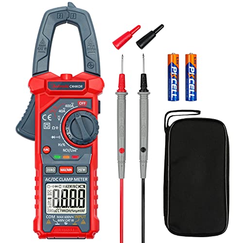
Versatile Digital Clamp Meter: Accurately measures AC/DC Current, AC/DC Voltage, Capacitance, Frequency, Duty Cycle, Resistance, Diode, Continuity and Live Wire Tests. This clamp meter is a really useful tool for solving industrial and household electrical issues.

Important Tips - This CM2K0R clamp meter can not test DC Current. To measure the AC Current you need to clamp the meter around one of the wires and not the whole power cord. Ensure the conductor to betested is in the center of the clamp head. The clamp Jaw is only used to measure current. Do not measure voltage by clamping the conductor being measured.
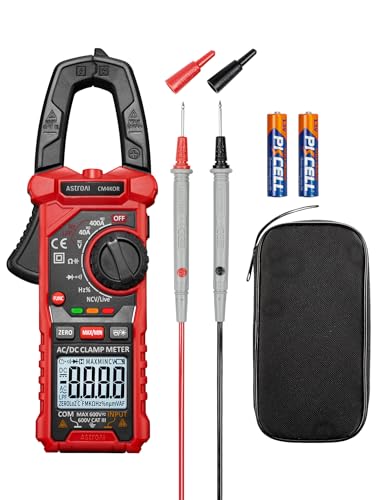
Versatile Digital Clamp Meter: Accurately measures AC/DC Current, AC/DC Voltage, Capacitance, Frequency, Duty Cycle, Resistance, Diode, Continuity and Live Wire Tests. This clamp meter is a really useful tool for solving industrial and household electrical issues.
Step 2: Clamp the Meter Jaws Around One Wire
To accurately measure current using a clamp meter, you must clamp the jaws around only one wire at a time. Fully open the jaws using the trigger, then carefully position the isolated conductor inside. Ensure the jaws close completely around the wire so the sensor can consistently detect the magnetic field. Never clamp both the live and neutral wires together, as their magnetic fields cancel each other out and produce a near-zero reading. The conductor should be insulated unless your meter explicitly allows measurement on bare wires. Keep the wire away from the jaw tips and center it within the clamp for optimal accuracy. Hold the clamp steady during measurement, as movement can affect reliability. A secure, centered clamp on a single insulated conductor ensures a valid and consistent current reading. For comparison, this method of single-wire clamping is similar to the approach used when handling electrical connectors like MC4 connectors, where isolating one conductor at a time is critical for safe disconnection. This method contrasts with measuring voltage, where an inverter or converter may require different connection strategies depending on the power solution. When choosing a clamp meter, reviewing top solar panel picks can help ensure your equipment matches the quality and value of your overall system.

Package Content: 20 Pcs M3 simplex bolt wire rope clips for 1.5-3mm diameter wire cable and free Wrench. Please read the detailed dimensions in the picture carefully before purchasing

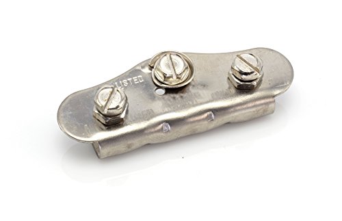
These grounding clamps provide a secure bonding connection between a copper ground wire and the metallic frame of an electrical meter pan.
Step 3: Center the Wire and Read the Stabilized Value
Center the conductor in the clamp’s jaws using the alignment marks as a guide to ensure the magnetic field is detected uniformly. Off-center placement can introduce measurement errors, especially at low currents. Proper wire placement—keeping the single conductor isolated and perpendicular within the jaw’s center—is essential to avoid cancellation effects from nearby wires. For example, when measuring in a solar home setup, ensuring accurate readings is critical for evaluating solar-powered battery performance. Understanding how inverter generators regulate power output can help clarify why stable current measurements are necessary for sensitive electronics.
Once the wire is properly centered, wait for the reading to stabilize. Allow the LCD to settle fully before recording the value. Fluctuating readings usually indicate shifting wire placement or movement, so recheck and hold the clamp steady. Use your multimeter’s auto-hold feature to automatically capture the stabilized value, which helps improve accuracy in noisy environments. Confirm that the range setting on your meter matches the expected current, and only record the measurement when the reading remains steady long enough to ensure accuracy.
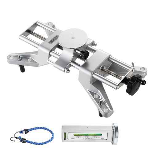
Precise Camber Measurement: This wheel clamp & magnetic adapter kit clamps to the rim without detaching the tire. The magnetic bubble gauge delivers 0.5° accuracy, reliably measuring camber to reduce uneven tire wear and improve handling stability

VERSATILE CLAMP METER: Measures AC current and NCVT via clamp; AC/DC voltage, resistance, and continuity via test-leads; temperature via thermocouple

【AUTO-RANGING METER】Automatic select the appropriate decimal point place due to auto-ranngig function, suitable for 600A AC Current, AC/DC Voltage(600V), ,Temperature, (200Ω-20MΩ) Resistance Measurement.
Measure AC and DC Current With Your Clamp Meter
Before measuring current, disconnect test leads and keep your fingers behind the tactile barrier. To measure AC current, open the jaws of your clamp meter around a single conductor and wait for the reading to stabilize. For DC current, perform a zero adjustment with the jaws closed and empty to eliminate offset error. Then clamp around only one DC conductor; clamping both supply and return wires cancels out the reading. Make sure the wire is centered in the jaw opening for a more accurate measurement, especially with DC, as off-center placement can cause more noticeable drift. Hold the clamp steady until the display settles before recording your readings. For installations like a solar array, correct connections are essential to ensure safety and proper system operation. If you are measuring near a power inverter in your vehicle, remember that the inverter’s output can introduce electrical noise that may affect the clamp meter’s accuracy. Always ensure the breaker box is properly prepared and de-energized before making any high-current measurements near distribution panels.
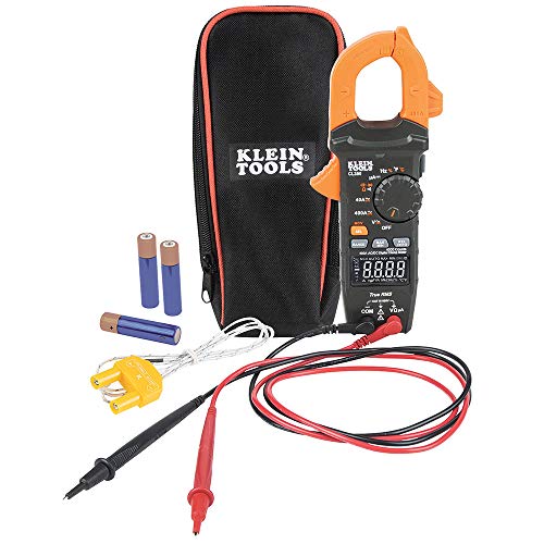
VERSATILE CLAMP METER: Measures AC/DC current and NCVT via clamp; AC/DC voltage, resistance, continuity, frequency/duty cycle, DC microamps, diode test and capacitance via test-leads; temperature via thermocouple
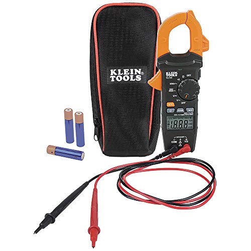
VERSITILE CLAMP METER: Measures AC current and NCVT via clamp; AC/DC voltage, resistance, and continuity via test-leads

【TRUE-RMS AC DC CLAMP METER】This multimeter can accurately measure AC/DC current, AC/DC voltage, temperature (thermocouple included), NCV, capacitance, frequency, resistance, continuity and diode. Good help for troubleshooting the household solar system, automotive and industrial electrical issues, perfect for electricians, DIY, professionals, etc.
Measure Voltage, Resistance, and Continuity With Test Leads
To measure voltage, resistance, or continuity with test leads, you need to switch the leads into specific ports on your multimeter. For voltage measurements, insert the black lead into the common (COM) port and the red lead into the voltage, resistance, and frequency (VΩHz) port. Rotate the dial to the appropriate voltage setting, selecting either AC or DC based on your circuit. Connect the probes in parallel across the load—meaning across the points where you want to measure voltage. Always verify the correct symbol appears on the display to ensure your measurement is accurate and you’re testing the correct parameter.
For resistance and continuity testing, insert the red lead into the shared Ω jack. Select the resistance function on the dial, using the SEL button if the meter offers multiple ranges. Before probing the circuit, disconnect power completely to prevent damage or inaccurate readings. Isolate at least one side of the component to get a reliable measurement. To check continuity, short the probes together first; a beep indicates low resistance below your meter’s threshold, confirming continuity. If the display shows OL (over limit), it indicates an open circuit, not a sensor error. Proper lead placement and ensuring the circuit is dead are crucial for obtaining accurate measurements and protecting your multimeter. Understanding the resolution and accuracy of your meter helps you choose the right model for precise readings. For a more integrated home energy solution, consider solar roof shingles that combine roofing and power generation. When troubleshooting solar equipment, you may need to perform a system power cycle to clear certain faults without requiring a full component replacement.
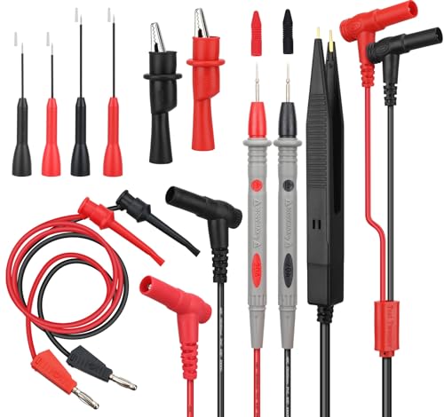
PROFESSIONAL GRADE SAFETY – The SWANLAKE test leads set is CAT III 1000V rated and supports up to 20A, ensuring reliable safety for high-voltage electrical testing with most multimeter and clamp meter brands

CERTIFIED HIGH SAFETY – Rated CAT.III 1000V and CAT.IV 600V, this multimeter test lead kit supports up to 10A, offering safe, dependable testing for voltage, continuity, and resistance across electrical, automotive, and industrial

All-Weather Silicone Flexibility: 40 in modular multimeter test leads / volt meter leads stay supple from deep cold to engine heat
5 Clamp Meter Accuracy Tips (Center, Zero, Range, Hold)
To ensure consistent accuracy with your clamp meter, follow five essential practices. First, always center the conductor fully within the jaw opening. Proper centering ensures a correct magnetic field reading; placing the conductor off-center distorts the field and reduces linearity. Second, zero the meter when measuring DC current by pressing the ZERO button with the jaws open. This step compensates for residual core magnetism and is critical for precise DC readings. Third, choose the correct measurement range: use auto-range for quick, convenient readings or select a manual setting for more stability. Avoid setting too high a range, which reduces resolution, or too low, which risks overload. Fourth, use the HOLD function only after the reading stabilizes; it freezes the display to make recording safer and easier. Finally, always double-check that the jaws are fully closed with no air gaps before taking a measurement. Combining these practices—centering, zeroing, correct range, and proper use of HOLD—will help ensure your readings are repeatable and trustworthy. For comparison, a 100-watt solar panel can power small DC appliances, but its current limits require careful measurement to avoid overload.
Common Clamp Meter Mistakes and How to Fix Them
Even with proper technique for centering, zeroing, range selection, and hold usage, several common clamp meter mistakes can still distort your readings. First, never clamp more than one conductor at a time. Clamping both the live and neutral wires cancels out the magnetic fields, resulting in a zero reading. To avoid this, isolate a single current-carrying conductor, which is a key measurement technique. For conducting safety, always ensure you’re on the correct live wire and not the neutral.
Another frequent mistake is selecting the wrong mode. Measuring current in voltage mode risks damaging your meter. Always verify whether you need AC or DC current mode before clamping. Proper jaw closure is also crucial; incomplete or loose closure degrades accuracy. Fully seat the conductor in the jaw’s center and close the clamp completely.
Finally, do not overlook the condition of your meter. Loose connections, demagnetization, or outdated calibration can cause erroneous results. Regularly inspect your clamp meter for mechanical looseness and verify its calibration status to maintain measurement reliability.
Fix Unexpected Clamp Meter Readings (Zero Drift, OL, Negative)
When unexpected readings like zero drift, OL, or negative values appear, systematically diagnose and correct each issue instead of assuming the meter is faulty. For zero drift, always use the zero or null function before taking measurements, ensuring the meter is in the same position and near the same conductor. Persistent drift may suggest a sensor problem; some meters permit fine adjustment with a trimpot, but follow proper calibration procedures. Battery influence can also cause baseline shifts; replacing low batteries often resolves this issue, as loose internal nuts on terminals frequently cause high resistance faults that mimic drift.
An OL (overload) or open circuit reading indicates the meter is encountering a voltage or current beyond its range or a broken connection. Switch to a higher range if available on manual meters. In resistance mode, check probes and connections for continuity and integrity.
A negative DC reading typically results from reversed test leads or clamp orientation. Reverse the clamp or probe direction to correct this. If a negative value appears in AC mode, ensure you’ve selected the correct measurement mode. Always clamp around a single conductor with the jaws fully closed to avoid measurement errors.