
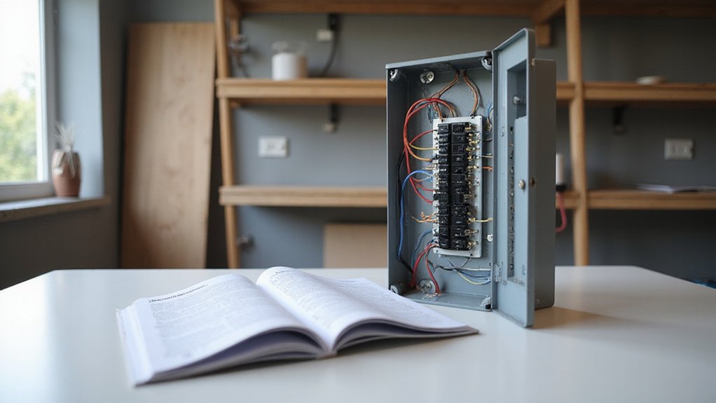

Installing a breaker box might seem daunting, but knowing the right steps can make it manageable and safe.
Whether you’re upgrading your panel or setting up a new circuit, proper wiring is crucial for safety and compliance.
By understanding the basics, you can ensure your installation works smoothly and passes inspection.
Keep reading for the full step-by-step guide to wiring your breaker box correctly.
Shut Off Main Power Before Breaker Box Wiring
Before opening a breaker box for wiring, ensure it is fully de-energized. Simply flipping off individual breakers does not guarantee safety because utility power may still be present upstream. The safest approach involves isolating the entire panel by applying a physical lockout device with a padlock on the main breaker. This prevents accidental re-energization during work. Follow the proper shutdown sequence: turn off all individual breakers first, then switch off the main disconnect. Use a properly rated voltage tester to verify that the panel is dead—check it against a known live source before testing the panel, and recheck afterward to confirm zero voltage. Remember, utility power can still be present even with the main breaker off unless locked out. Keep grounding procedures in place throughout the process to prevent shock hazards. When working on the panel, assume every conductor is live until verified dead, and consider using non-conductive enclosures to reduce shock risk. For projects involving multiple panels, such as a garage sub panel, proper identification of panel types prevents accidental electrical hazards. Additionally, understanding how a solar charge controller regulates voltage from panels helps ensure safe integration of backup power sources. For choosing replacement breakers, refer to reviews of top battery picks with terminals to compare quality and performance. A similar principle applies when disconnecting a car battery: always remove the negative cable first to minimize the risk of short circuits against the chassis.
Choose a Code-Compliant Location and Mount the Panel
Choose an open, accessible indoor space such as a basement, garage, or utility room to mount your panel. Avoid locations like bathrooms, clothes closets, stairways, and fire-rated partitions to meet code requirements. The panel’s height is especially important: the highest breaker handle must not be more than 6 feet 7 inches above the finished floor. Position the box so all overcurrent devices are within reach without a ladder. For a generator setup, a Square D interlock kit ensures you can safely isolate utility and generator power. Ensure there is at least 36 inches of clear working depth in front of the panel, 30 inches of width, and a vertical clearance of 6 feet 6 inches. For environmental protection, keep the area dry and well-ventilated—avoid storage-heavy zones that might block access. If outdoor installation is necessary, use a NEMA 3R weather-rated enclosure. Mount the panel plumb on a solid surface and center it within the designated zone to facilitate safe servicing. Selecting a busbar with an appropriate ampacity rating ensures the panel can handle the total load without overheating. Reviewing automatic transfer switches can help you select a model that coordinates with your interlock setup for seamless power transition.
Strip Knockouts and Feed Service Conductors In
Begin by locating the panel’s knockouts and removing only those needed for the service raceway, connectors, or cable clamps. Leave all unused openings intact to maintain enclosure integrity. Use a punch or screwdriver for knockout removal, and check local code requirements for specific guidelines. After removing the necessary knockouts, install conduit or connectors and secure them with locknuts from inside the panel. Ensure that bonding locknuts or listed bonding bushings are used at ringed knockouts for metal service raceways to maintain proper grounding.
Next, run a fish tape through the conduit opening from inside the panel to the exterior entry point. Carefully pull the service conductors through the conduit to avoid damaging the insulation at the panel edge. Route the phase, neutral, and grounding conductors only through the designated knockout openings—do not create or use improvised openings. For conductors 4 AWG and larger, install a bushing to protect the insulation from abrasion. Follow the conduit manufacturer’s installation instructions to preserve enclosure integrity and bonding continuity throughout the setup. For specialized equipment like a solar inverter, a hard reset may also be required after wiring is complete to clear system faults and restore normal operation. To verify that no current is flowing on the grounding conductor after installation, use a clamp-on amp meter to check for stray current, ensuring the system is properly bonded and safe. For extended power needs during outages, consider a portable power station that provides reliable backup for essential circuits.

💎 Punch Clean, Round Holes: Our knockout punch set ensures smooth operation and clean hole edges, resulting in uniform hole size and lovely, round holes.

COMPLETE 4-DIE PROFESSIONAL SET: Includes 4 sets of precision dies for standard conduit sizes: 1/2", 3/4", 1" and 1-1/4". Perfect for creating clean, burr-free holes in electrical panels and junction boxes. Designed for professional electrical standards. Actual hole diameters are: 1/2"(0.885"), 3/4"(1.115"), 1"(1.362") and 1-1/4"(1.701"). Ensure a perfect fit for your conduits every time.

Quality and Durability: the knockout seal is crafted using iron material, ensuring they are robust and long lasting; They are designed to through everyday wear and tear, providing a proper solution for electrical endeavor; Available in a quantity of 12 pieces per pack, they are an ideal choice for those seeking quality and durability
Connect Main Breaker Box Wiring: Hot, Neutral, Ground
To connect the main breaker box wiring—hot, neutral, and ground—you need to land each conductor properly on its designated terminal or bus bar. Begin by terminating the two hot conductors, usually colored black and red, onto the main breaker’s line lugs. Ensure each connection is tightened to the manufacturer’s specified torque to prevent loose connections that could lead to arcing hazards. Next, land the white neutral conductor on the neutral bus bar, which is bonded to the enclosure and the grounding system at the service equipment. This bonded neutral bus serves as the Neutral bonding point. Finally, connect the bare or green grounding conductor to the ground bus bar. Proper placement of the grounding conductor ensures a low-impedance path for fault currents. Each conductor should be secured using a dedicated screw, and it is crucial to verify the color coding and torque settings before proceeding. An interlock kit prevents main and generator breakers from being on simultaneously, adding critical safety to this installation. Once completed, your main service entrance wiring will have hot, neutral, and ground conductors all correctly and securely connected.

【Compatible Models】Generator Interlock Kit Compatible with Square D QO or Homeline 150 or 200 amp panels.

QYZZRS Generator Interlock Kit Compatible with Eaton Cutler Hammer 100 Amp and 125 Amp Panels Breaker.

Great Compatibility: Our Generator interlock kit is compatible for Eaton Cutler Hammer 100 Amp and 125 Amp Panels
Bond Neutral in Main Panels (Isolate in Subpanels)
The neutral-to-ground bond should only be in the main panel, not beyond it. The National Electrical Code (NEC) 250.24(A)(5) mandates that neutral grounding occurs at the service disconnect, which is typically the main panel. Bonding the neutral and ground at this point establishes a single fault-clearing path for the entire system. When wiring a new circuit, such as a dryer, the correct dryer plug connections to the breaker box ensure that the grounding path is properly established back to this main bond. Downstream, you must keep the subpanel isolated to prevent current from flowing on the grounding conductors and metal parts. To do this, you remove any bonding screw, strap, or jumper linking the neutral bus to the subpanel’s enclosure. Leaving a bond in place causes normal neutral current to flow through the equipment grounding system, creating an improper parallel path. This can lead to shock hazards and interfere with proper fault clearing. Instead, install a separate grounding bar bonded to the subpanel chassis and connect all equipment grounds there. Keep the neutral conductors on an isolated neutral bus that does not touch the enclosure. Improper bonding, such as a bonding screw incorrectly bonding cabinet and neutrals in a sub panel, directly violates safety standards and must be corrected to ensure proper separation. Proper bonding only at the main panel and subpanel isolation are critical for safety and code compliance. Just as a solar inverter’s lifespan depends on stable electrical conditions, consistent grounding and bonding integrity prevents stray currents that degrade system components over time. For reliable long-term performance, always use a charger with proper voltage regulation to maintain stable charging conditions.
Size Each Breaker and Wire by Circuit Load
To size a breaker properly, you first need to determine whether each circuit’s load is continuous—expected to operate for three hours or more—or non-continuous. For continuous loads, multiply the amperage by 1.25 to calculate the design current. This adjustment ensures the breaker can handle prolonged operation without tripping unnecessarily. For non-continuous loads, add up their actual amperage at 100%. Once you have the total load, select a breaker rated at or above this value, using standard sizes such as 15 A or 20 A. Ensure that the breaker rating does not exceed the wire’s permissible ampacity—pairing a 14 AWG wire with a 15 A breaker or a 12 AWG wire with a 20 A breaker is appropriate. Never install a breaker larger than the wire’s rated capacity, as this leaves the conductor unprotected and creates a safety hazard. Always verify that your chosen breaker complies with the electrical code’s conductor ampacity requirements. For solar installations using these panels, choosing a solar charger without battery can simplify system design by directly powering loads or feeding a grid-tied inverter. For solar installations using these panels, the MC4 connectors provide a reliable and weather-resistant connection to the breakers. When selecting a battery for the system, note that AGM batteries are better suited for deeper discharge cycles than standard flooded batteries.

Single pole, 15 Amp, 120V type QP Circuit Breaker

RELIABLE CIRCUIT PROTECTION: Designed as a 15 amp circuit breaker, this unit offers dependable protection for residential and light commercial electrical systems. Prevents overloads and short circuits.
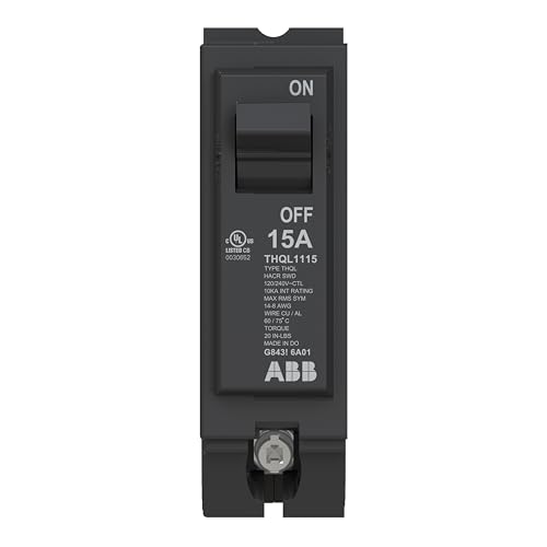
POWER PROTECTION - This thermal magnetic circuit breaker provides protection for residential and commercial electrical systems. ABB's 15A single-pole breaker protects again electrical faults to enhance safety.
Cut and Strip Branch Circuit Wires to Length
After selecting the appropriate breaker and wire size for each circuit, cut and strip the branch circuit conductors to the correct length. Leave approximately six inches of slack per conductor to prevent tension on the terminals, but trim each wire so that excess length does not overcrowd the panel. For insulation stripping, remove only 19 mm (3/4 inch) of sheathing or match the exact length required by your termination device. Removing too much bare copper increases the risk of short circuits, while too little can weaken the connection. When selecting your breaker and wire setup, refer to top battery tray reviews to find compatible mounting solutions that keep your panel organized. This careful planning also helps you avoid the higher running costs associated with inefficient power conversion setups, especially when alternating between AC and DC sources later on. A home-made stripper setup must follow safety limits to avoid damaging the conductor.
Before working inside the panel, confirm that it is de-energized using a voltage tester. When cutting the wire, do so cleanly to avoid nicking the conductor, which can compromise its integrity. When stripping, do so evenly to ensure a good connection and prevent damage to the conductor. Proper preparation of the wires helps ensure safe, code-compliant terminations and facilitates easier breaker placement later on.

✅ 8 inch Professional Wire Stripper: Cuts, strips wire and loops 10-22 AWG Solid copper wire or aluminum cables.high carbon alloy steel with accurate stripping.
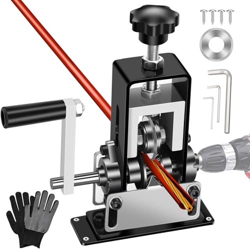
【Easy Wire Stripping】: Our wire stripper machine streamlines the wire stripping process, saving time and effort. Ideal for both DIY enthusiasts and professionals, its adjustable settings ensure precise and clean wire stripping, minimizing the risk of wire damage.

👍【 Effortless Wire Stripping】TORRIDE Manual Wire Stripping Machine saves time and effort with its automated wire stripping process, making it perfect for DIY enthusiasts and professionals alike. The adjustable settings ensure precise and clean wire stripping, minimizing the risk of wire damage.
Land Branch Circuits on Correct Breaker Box Bus Bars
Before landing branch circuits, verify that each breaker matches the panel’s bus bar design. Using the wrong breaker type can prevent proper contact and cause overheating. Consult the panel’s label to identify the designated breaker positions. Relying solely on physical fit does not guarantee bus compatibility.
Ensure that breaker types align with the panel’s listed series, mounting style, and connection method—whether plug-in or bolt-on. Tandem or quad breakers should only be installed in slots explicitly marked for them. For hot conductors, terminate them on the breaker, not directly on the bus bar. Confirm that the breaker seats fully onto the bus stab to ensure proper contact and safety. Just as breaker fit affects electrical connections, using a ferrule crimping tool ensures secure and reliable terminations for wire ends.
On 120-volt circuits, land one hot pole; for 240-volt circuits, land two adjacent hot poles. Avoid misplacing neutrals in subpanels; they must be connected to an isolated neutral bar, separate from the equipment ground bar, to comply with electrical codes and prevent potential issues.

CHBAB1020 C-H BAB1020; 20A QCKLAG BOLT ON 1P 120/2

Square D - QOB320 - Bolt On Circuit Breaker, 20 Amps, Number of Poles: 3, 240VAC AC Voltage Rating

CHBAB2030 C-H BAB2030; 30A QCKLAG BOLT ON 2P 120/2
Inspect Terminations and Route Wires Cleanly
Inspecting terminations and routing wires cleanly is essential for a safe and reliable electrical connection. Start by performing a detailed terminal inspection: ensure each lug is fully seated, with no insulation trapped under the clamp, and check for any loose strands protruding. Apply the torque specified by the manufacturer exactly—document this value to confirm compliance. Look for signs of discoloration, pitting, or heat damage; reject any terminations that show these issues. Verify that the stripping length leaves no bare copper beyond the terminal, preventing potential contact or corrosion.
Next, focus on organizing the wires for clarity and safety. Route conductors along panel edges in orderly paths, maintaining them within designated gutters and away from breaker handles. Separate phase, neutral, and grounding conductors where possible to facilitate troubleshooting and prevent accidental contact. Maintain the minimum bend radius at terminals to avoid stressing or damaging the conductors. Allow enough slack to prevent tension but avoid creating excessive loops that can clutter the panel. Keep wiring away from sharp edges and moving parts to prevent abrasion or strain that could compromise the connections over time.
Label Every Circuit and Test After Power Restored
Label every circuit in the panel after power is restored. Turn off one breaker at a time and identify what it controls using a plug-in tester or lamp. Confirm the affected areas with the tester, making sure to match the circuit to its actual load—avoid vague descriptions like “lights.” Mark spare positions as “Spare” and empty slots as “Space.” Ensure that the final labels reflect the actual energized circuits found during testing, not assumptions.
After wiring is complete and power is turned back on, verify each outlet, light, and appliance functions correctly. Stand on a dry surface and keep the panel’s deadfront in place to prevent accidental contact with live parts. Double-check that all labels correspond to real loads and that the circuit breaker operates as expected. Walk through the panel one last time, confirming every breaker’s label matches its load, and note any shared neutrals or special wiring arrangements for future safety.