


If you’re figuring out how to wire a solar array, you want to ensure everything is done safely and correctly. Proper wiring is key to maximizing efficiency and avoiding hazards, but it can seem complicated without guidance.
By following the right steps, you’ll be able to connect your panels properly and get your system up and running smoothly.
The detailed process starts just below.
Gather Tools and Verify Voltage Before Wiring Solar Panels
Gather the appropriate tools and verify the voltage before wiring your solar panels. Use a digital multimeter calibrated to accurately measure DC voltages up to 1,000 V or higher, with a safety rating of CAT III or CAT IV. Match your test leads to your system’s voltage to prevent damage or inaccuracies.
Set your multimeter to DC voltage mode. Connect the red probe to the positive terminal of the panel or string and the black probe to the negative terminal. Conduct measurements in full sunlight to get reliable readings. Confirm that the open-circuit voltage (Voc) aligns within 10% of the manufacturer’s specifications. A positive reading indicates correct polarity; a negative reading shows reversed wiring, which needs correction before proceeding. Selecting a high-quality unit with efficient solar converters ensures your inverter receives stable voltage and maximizes energy harvest. For reliable connections, choose a battery with terminals that offer quality for both performance and value.
Lastly, check wiring paths for continuity and grounding integrity, and verify terminal torque on all connections. Avoiding voltage mismatches also protects your power station from premature aging, similar to how overcharging or deep discharging shortens portable power station lifespan. These steps help prevent downstream issues and ensure your array is prepared for safe and efficient final interconnection.
Wire Solar Panels in Series for Higher Voltage
Wiring solar panels in series increases the total voltage of the array. To do this, connect the positive terminal of one panel to the negative terminal of the next, forming a chain. The total voltage is the sum of each panel’s Vmp (maximum power voltage), while the current remains the same as a single panel’s rating. For example, connecting four panels rated at 31.5 Vmp and 13.0 A results in approximately 126 V at 13.0 A. Raising the voltage like this reduces wire losses over long distances, improving overall efficiency. Just ensure all panels in the string have closely matched voltage ratings to prevent performance issues. Always verify that the open-circuit voltage of the entire string does not exceed your charge controller or inverter’s maximum input limit. Series wiring works best when the panels have similar exposure to sunlight and comparable specifications. This approach sums voltages while current remains constant, emphasizing safe handling of higher voltages. For reliable connections, use MC4 connectors to ensure compatibility with top-rated panels. Using high-quality cables with lugs is equally critical for minimizing resistance and ensuring safe, durable connections in your array. While upgrading your system, you might also consider a portable power station with built-in wall outlets for dependable backup charging during off-grid setups.

Quick Parallel 2 Solar Panels: BougeRV 1 to 2 Y branch cable can parallel 2 solar panels. The kit includes 1 male to 2 female (M/FF) and 1 female to 2 male (F/MM) solar connectors

Package Included: 6 pairs solar panel connectors Male and Female + 6 pairs solar connector pins (male and female) + 1 pair of spanners

Combine Solar Panel Strings in Parallel for More Current
Combining solar panel strings in parallel increases the total current output while maintaining the same voltage. When wiring multiple strings this way, you add each string’s current together, which boosts overall system amps without changing the voltage level. This setup is ideal if your goal is to increase current capacity for higher power output at a fixed voltage. For reliable connections, use DIN rail terminal blocks to organize and secure your wiring neatly within the combiner box. Always disconnect the negative battery cable first when working on the battery to prevent short circuits and accidental sparks.
However, to prevent issues like current imbalance, it is essential to perform string matching. Ensure each string has an identical voltage before paralleling, as mismatched voltages can cause circulating currents that reduce system efficiency and potentially damage components. Each parallel string must have its own fuse or breaker at the combiner box to protect against backfeed and overcurrent conditions, as frequent breaker tripping can indicate improper protection or an overloaded circuit.
Your downstream wiring must be rated to handle the combined current load, including derating for continuous operation. Using larger-gauge wire reduces voltage drop across longer distances and helps maintain system performance. Also, check your module manufacturer’s maximum series fuse rating. If the total short-circuit current multiplied by 1.56 exceeds this rating, string-level protection becomes mandatory. Keeping your string designs consistent simplifies protection, troubleshooting, and overall system performance.


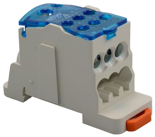
Product Type: Power Distribution Terminal Block
Connect Strings to the Combiner Box and Run Home Runs
Connect each solar string to the combiner box by routing the home-run conductors into the appropriate bus bars. Start by cutting MC4 extensions into separate positive and negative leads. Pull these leads through conduit into the box, ensuring a tidy and protected connection. Strip the insulation from the conductors to the manufacturer-specified length, then land the positive lead on its fuse position and the negative on the negative bus bar. Keep all string breakers off during this process to prevent accidental energization. Use wire size—typically 8 or 10 AWG—that accounts for voltage drop, aiming for under 2 percent loss over the run. Follow grounding procedures by connecting the equipment grounding conductor to the dedicated lug and bonding it to the enclosure. Before tightening connections, verify the correct polarity with a voltmeter to prevent electrical issues. Ensure that the DC breakers are rated for each string as they connect to the PV wires inside the box. A charge controller’s overcurrent protection rating must match these breaker ratings to safeguard the system.

Professional Crimper - This crimper features an efficient ratchet mechanism and finish-machined crimp die for a solid crimp. This crimping tool fits perfectly with solar connectors - suit for AWG 14-8 (2.5-10mm²)

The battery terminal connector is made of high-quality pure copper material, which is resistant to high temperature and corrosion and achieves maximum conductivity.

🌅 Solar Cable AWG 8/10/12 Wide Compatibility: This solar crimping tool is expertly designed to be compatible with a wide range of connectors and cables used in solar PV systems. It fits wire gauges from AWG 8 to AWG 12 (10 - 4mm²), ensuring that you can handle various projects without the need for multiple tools. Whether you are working on a small - scale residential solar setup or a large - scale commercial installation, this crimper has got you covered.
Hook Up DC Wires to the Inverter and AC Service Panel
Connect the inverter’s AC output through conduit to an AC disconnect, which provides a safe point to shut off power for maintenance or in case of an emergency. From there, wire the disconnect to a dedicated backfed breaker installed in the main service panel. This breaker allows the inverter’s power to feed back into the electrical system safely and complies with code requirements. A properly selected disconnect switch isolates the solar array from the grid during servicing, ensuring technician safety.
Ensure that the conductors—typically copper or aluminum wire—are sized appropriately for the inverter’s continuous output current, as specified by the manufacturer’s documentation and electrical codes. Overcurrent protection devices must be rated correctly to prevent overloads or short circuits without nuisance tripping. If the inverter stops producing power, a reset procedure may resolve the issue by clearing internal faults and restoring normal operation. Before beginning any wiring, verify that the main breaker is off and lock it out to prevent accidental energization, as this is a critical safety step that protects against live busbar exposure.
In the main service panel, connect the backfed breaker to the busbar, making sure that the total busbar load stays within its rated capacity. Keep the neutral and ground conductors separate throughout the system; bond the neutral and ground only at the main service equipment to prevent potential electrical hazards or ground loops in subpanels. Properly tightening all connections and verifying correct wiring are essential steps to ensure safety and reliable operation.

With IP65 waterproof breaker box,Suitable for outdoor installation, such as connecting solar energy, car charging posts, etc.the transparent cover also make it easy to check the status of the circuit breaker.

FUNCTIONS: Used to protect 48~500VDC OR 90~480VAC circuit from overload and short circuit damage and 12~48VDC from overload damage, and can also be used for control and isolation. Size: 54MM x 80MM x 75MM, Fit for 35mm DIN rail.
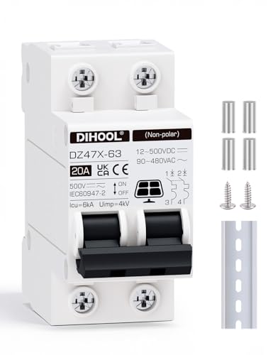
FUNCTIONS: Used to protect 48~500VDC OR 90~480VAC circuit from overload and short circuit damage and 12~48VDC from overload damage, and can also be used for control and isolation. Size: 54MM x 80MM x 75MM, Fit for 35mm DIN rail.
Test System Polarity, Voltage, and Code Compliance
Verify the polarity of every PV string cable before closing disconnects or inserting overcurrent protection devices. Use a suitable multimeter to ensure the positive conductors are consistent through modules and combiner boxes. Reversing the polarity of parallel strings can cause catastrophic failure, so thorough verification is essential. After confirming polarity, measure the string’s open-circuit voltage (Voc). The reading should be within ±5% of the calculated Voc at the measured irradiance and temperature, which helps verify correct module count and series wiring. Performing this step prevents immediate equipment damage and ensures the system’s electrical integrity before energization. In a home setup, terminal blocks simplify wiring by securely connecting multiple conductors without soldering or twisting. The breaker box itself serves as the central point where these connections are protected from overloads that could otherwise cause fires. For reliable long-distance daisy-chaining of monitoring equipment across strings, RS485 cables are often used to handle communication without signal degradation. According to IEC 62446-1, polarity checks are classified as Category 1 tests and must be completed during commissioning. The NEC 690.31(B)(2) standard requires clear identification of DC conductors at all terminations, such as plus (+), POS, or minus (−). Document each string’s pass or fail status along with the voltage readings in your commissioning report. These checks need to be done prior to paralleling strings because skipping them significantly increases the risk of faults, equipment damage, or inspection failure.