
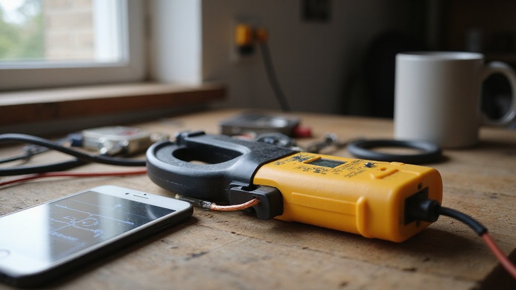

Ever wondered how you can measure current without breaking the circuit? A clamp meter makes this possible by detecting magnetic fields around a wire.
It works quickly and safely on live circuits, giving you accurate readings without disconnecting anything.
Keep reading to learn how to master this handy tool.
What Is a Clamp Meter and How Is It Different From a Multimeter?
A clamp meter is a specialized electrical testing tool designed to measure current without breaking the circuit. It works by encircling a single conductor with its hinged jaw, allowing you to obtain a current reading simply by clamping onto the wire. This makes it much faster and safer for live-wire checks compared to a multimeter, which requires you to disconnect the circuit and insert test leads in series. For safety and prevention of damage, daily cleaning of the clamp meter’s jaw faces is recommended, just as you would maintain other tools to avoid debris buildup. Models that offer the best top battery picks with terminals provide reliable power for field use, ensuring consistent performance during testing. When selecting a model, consider the jaw opening size to ensure it can fit around larger gauge conductors as detailed in the guide to extending battery cables.
The key difference between a clamp meter and a multimeter lies in their primary functions. A clamp meter is ideal for measuring high current in field settings like HVAC systems or motor troubleshooting because it can handle large currents with ease. On the other hand, a multimeter excels at precise measurements such as testing resistances, voltages, and low current components, making it suitable for detailed diagnostics and component testing.
Proper tool maintenance ensures accurate readings. Keep your clamp meter’s jaw faces clean and free of debris. When not in use, store it with the range switch set to OFF to preserve battery life. This small habit helps maintain its reliability over time.

SAFE INSULATION: High-quality insulating plastic shells prevent short circuits during testing, ensuring user safety during electrical measurements

SAFE INSULATION: High-quality insulating plastic shells prevent short circuits during testing, ensuring user safety during electrical measurements.

Get precise HVAC insights: Effortlessly measure temperatures from -40°C to 150°C (-40°F to 302°F) with ±0.5°C (±0.9°F) accuracy. Stay ahead of HVAC issues for ultimate comfort.
The Simple Physics of Clamp Meter Current Sensing
When you clamp a meter around a conductor, you’re not measuring the current directly but detecting the magnetic field produced by that current. The magnetic field forms concentric loops around the wire, with its strength proportional to the current flowing through it. The clamp jaws serve as a magnetic core, focusing this magnetic flux into a defined pathway. Inside the core, either a current transformer or a Hall-effect sensor detects the magnetic flux. For alternating current (AC), the changing magnetic field induces a current in a secondary winding, scaled according to the turns ratio. For direct current (DC), a Hall sensor positioned in a gap produces a voltage proportional to the flux density, which the meter then translates into a current reading. This entire process allows you to measure current without making direct electrical contact with the conductor. Unlike the direct-contact approach of a digital multimeter, this clamp method works by sensing the magnetic field around the wire. This same principle of focusing magnetic fields is also used in a crimping tool to securely deform a metal connector around a wire. This non-contact sensing principle is also used in MC4 connectors to ensure safe and reliable connections for solar panel wiring.
How Clamp Meters Handle AC and DC Current Differently
AC-only clamp meters rely on transformer action to detect the magnetic field from alternating current. They induce a small voltage in a coil, which is proportional to the current, but only for AC signals. These meters cannot measure DC current because a steady magnetic field does not induce a change and thus cannot produce a measurable signal. A clamp meter’s main parts include the jaw, trigger, and display, which are essential for handling measurements. This limitation highlights why knowing the core working principles of solar panels helps in selecting the right monitoring equipment for your system.
Models that can measure both AC and DC currents use a Hall effect sensor. This sensor directly detects static magnetic fields generated by DC current. When the magnetic field is steady, the Hall sensor produces a voltage proportional to the current, allowing precise measurement of DC as well as AC.
To accurately measure DC, you typically need to zero or calibrate the Hall effect clamp before use. This step cancels sensor drift that can cause inaccuracies over time. For AC measurements alone, this zeroing step is unnecessary, simplifying the process.
When working on systems that include both AC and DC currents, choose a meter labeled as AC/DC capable—look for markings like A⎓. This ensures you won’t need multiple meters and can troubleshoot effectively across different power sources. Understanding how each type of clamp meter works helps ensure you select the right tool for the task, providing accurate readings and minimizing errors.
How to Properly Clamp a Wire for an Accurate Clamp Meter Reading
To ensure an accurate clamp meter reading, you must clamp around only one current-carrying conductor. Clamping around both hot and neutral conductors simultaneously cancels the magnetic field, resulting in a near-zero reading. For three-phase systems, isolate and clamp around only one phase conductor at a time. This method relies on the principle that AC currents produce a constantly expanding and collapsing magnetic field, measurable by the clamp’s sensors.
Center the wire within the jaw opening for the best accuracy. Most meters feature alignment marks—use these to position the wire correctly. Placing the wire off-center increases measurement error because the clamp’s magnetic field isn’t evenly focused. Keep the conductor centered to obtain a precise reading.
Make sure the jaws close fully and without gaps. A partially open or dirty jaw reduces the magnetic circuit’s integrity and distorts the measurement. Regularly inspect and clean the jaws to maintain full closure and optimal contact. Always keep your hands behind the barriers during this process to ensure safety.
Hold the clamp perpendicular to the conductor throughout the measurement process. Maintain a steady grip and avoid twisting or moving the meter while taking the reading. Proper jaw alignment and stable positioning minimize noise and improve measurement repeatability, especially on low-current setups. Keeping the wire centered within the jaws is critical for measurement accuracy.

VERSITILE CLAMP METER: CL120 measures AC current and NCVT via clamp; AC/DC voltage, resistance, and continuity via test-leads

VERSATILE CLAMP METER: Measures AC current and NCVT via clamp; AC/DC voltage, resistance, and continuity via test-leads; temperature via thermocouple
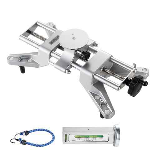
Precise Camber Measurement: This wheel clamp & magnetic adapter kit clamps to the rim without detaching the tire. The magnetic bubble gauge delivers 0.5° accuracy, reliably measuring camber to reduce uneven tire wear and improve handling stability
4 Common Clamp Meter Mistakes That Cause False Readings
Even experienced electricians can get false readings from a clamp meter if they make certain mistakes. One common error is clamping around multiple conductors. When you surround both live and neutral wires together, their magnetic fields cancel each other out. This results in a near-zero reading even if current is flowing. To ensure accuracy, always isolate a single wire when taking a measurement. For a solar array installation, after wiring the system, you should test with a clamp meter exactly as you would test a live circuit to verify correct connections before finalizing the setup. If you need to disconnect a wire, carefully break cable ties without damaging the insulation to avoid short circuits. For example, understanding the running costs of each option can help you decide which fits your specific setup.
Another frequent mistake is choosing the wrong mode. Using AC mode when measuring DC, or forgetting to zero the meter beforehand, can produce readings that seem normal but are actually incorrect. Additionally, selecting the proper range is crucial; using a range that’s too large can cause low currents to appear distorted or less precise.
Faulty jaws can also lead to inaccurate readings. Incomplete closure or mechanical looseness allows magnetic flux to leak, causing inconsistent or low readings. Dirt, misalignment, or damage to the jaws similarly impair measurement accuracy.
Finally, it is essential to check calibration regularly. A weak battery, calibration drift, or internal electrical faults can cause your clamp meter to give off unreliable readings without obvious signs. Always verify your meter’s condition before relying on its numbers. Remember, false confidence in incorrect measurements can be more dangerous than no reading at all.

【10000 Counts TRMS Clamp Meter】FNIRSI DMC-100 digital clamp multimeter provides stable TRMS measurement for AC/DC current up to 600A, voltage, resistance, capacitance, frequency, and temperature. It integrates NCV detection, live wire testing, continuity, and diode checks to support multi-function electrical diagnostics in maintenance and repair scenarios

⚡【DC AC Current Clamp Multimeter】This multifuctional clamp-on meter can accurately measures AC DC current with 400A/1000A ranges, 100mA/1A resolution;AC and DC Voltage to 1000V, Resistance to 60M ohms; Capacitor to 200μ farad; Frequency to 9.999m Hz; Temperarture -4~1832℉ (℃/℉ Optional), Test voltage 4V, can measure light-emitting diodes, and continuity test.
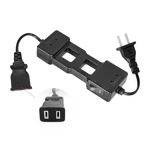
✅【AC Line Splitter】The Kethvoz 7400A is an AC line splitter with plug/receptacle, measures currents up to 15A without separating the load power cord.
5 Clamp Meter Limitations Every Beginner Should Know
Clamp meter accuracy can degrade if you don’t understand its limitations. First, accuracy drops significantly at low readings. Measurements below 10 percent of the meter’s full scale, like using a 400 A clamp for just a few amps, tend to be unreliable. Second, the position of the conductor inside the jaw is crucial. Placing the wire off-center or near the edge reduces magnetic coupling, leading to errors. Third, nearby conductors can interfere magnetically, distorting your reading unless you isolate the cable you’re testing. Fourth, waveform shape affects accuracy. Non-sinusoidal loads with high crest factors can push the clamp beyond its specified limits, resulting in skewed results. Lastly, without proper calibration, issues like DC offsets and zero drift can creep in. To maximize accuracy, always center the wire, select the appropriate range, and ensure the waveform is compatible with your meter’s specifications before measuring. For best results, treat each measurement like a battery cable soldering task requiring careful preparation and attention to detail. When choosing a meter for rooftop solar work, pay close attention to mounting system compatibility to ensure your readings are reliable under real-world installation conditions. For difficult-to-access panels, you might rely on a best circuit breaker to safely isolate circuits before testing.
Why Electricians Trust Clamp Meters for Safe Live Troubleshooting
Clamp meters allow you to measure current without opening the circuit, making them essential for live troubleshooting. They work by clamping around a conductor and detecting the magnetic field generated by current flow. This non-contact method enables you to measure live circuits safely, without direct contact with energized parts, reducing the risk of electric shock and equipment damage.
Since you don’t need to disconnect or insert test leads into live circuits, you save time and minimize downtime. This makes troubleshooting quicker and safer, especially in tight spaces or difficult-to-reach wiring within panels or feeders. The ability to quickly assess live current flow helps you pinpoint faults more efficiently.
To ensure safe use, always verify the clamp meter’s CAT rating—many are rated CAT III 600V—before use. Wear insulated gloves, keep yourself dry, and avoid any water contact. Regular calibration of your meter guarantees measurement accuracy, preventing false readings that could lead to unsafe situations. Start by scanning for overloads or imbalances, then use a multimeter for detailed checks if needed. Combining these safety precautions with the convenience of clamp meters ensures a safer, faster troubleshooting process.

True-RMS clamp meter: This multimeter can accurately measure AC/DC Current, AC/DC Voltage, Frequency or Duty Cycle, Resistance, Capacitance and also provides Diode, Continuity and Temperature tests. True RMS for accurate measurements on non-linear loads. Easy to use for labs factories and household

Digital clamp meter measures AC current to 400 amp, AC and DC voltage to 600 v, and resistance to 4 kilo ohms. Does not measure DC current

Compact, easy-to-use clamp meter with 30 mm large jaw taking measurements on large conductors