
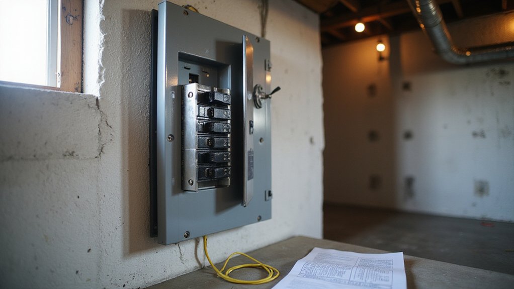

If you’re wondering how to safely install a generator interlock kit, you’re in the right place. The key is ensuring your kit matches your panel’s brand, model, and main breaker size to keep everything compliant and safe.
Proper installation stops backfeed and protects your system during power outages.
By the end of this guide, you’ll know how to select the right kit, install it correctly, and test your setup to ensure everything works smoothly.
Let’s walk through the steps to make your backup power setup both safe and reliable.
Match the Interlock Kit to Your Panel Brand and Model
To match an interlock kit to your panel, you must first identify the exact panel brand and model series. These kits are specifically designed to fit certain panels and rely on the breaker layout. Check the label on the enclosure door—common brands include Square D, Siemens, Eaton, and GE—to determine your panel’s manufacturer. Confirm the main breaker amperage, which is typically 100, 125, 150, or 200 amps, because the kit must be rated for your panel’s capacity. Measure the distance and throw direction between the main breaker and the backfeed slot; a kit that fits the brand may still not work if spacing or orientation do not match. Ensure you select a MET-listed, panel-matched kit—never opt for a generic or universal solution. Understanding how to read the display on your home electricity monitor can help you track load changes that affect interlock sizing. For easier installation, consider which kit includes clear instructions and compatible hardware as highlighted in reviews of the best interlock kits. Finally, verify your panel’s exact model number against the vendor’s compatibility chart to confirm a code-compliant and safe fit. For guidance on selecting the right component, reviewing reviews of the best isolator for battery systems can help ensure you choose a properly rated and reliable product.

【Compatible Models】Generator Interlock Kit Compatible with Square D QO or Homeline 150 or 200 amp panels.

Compatible Models: Generator interlock kit compatible with Siemens/Murray 100 Amp panels

Generator interlock kits are available for Square D QO and Homeline 150 and 200 amp panels.
Shut Off Power and Remove the Panel Cover Safely
To safely shut off power and remove the panel cover, start by turning the main service disconnect to the OFF position. Always stand to the side of the disconnect to reduce exposure to arcs. Remember, even with the main breaker turned off, service entrance conductors and main lugs may still be energized. Use a non-contact voltage tester to confirm that the circuit is dead before proceeding. Always follow the safest fix order to ensure that you resolve the most critical issues first without creating new hazards. This process mirrors the logic of why negative battery cables come off first, preventing accidental shorts and sparks. When removing a specific breaker later, you must follow a safe sequence to avoid contact with energized bus bars.
Ensure the area around the panel is dry; do not work in wet or damp environments. Verify that the flooring and enclosure are dry and intact. Wear tools rated for 1000 V AC insulation, along with safety glasses and appropriate gloves. Maintain a stable stance, avoiding contact with grounded surfaces to minimize risk.
Carefully remove the screws holding the dead front cover, supporting the cover as you do. Tilt the cover straight away from the panel to prevent internal parts from falling out or making accidental contact. Treat all internal components as live — do not touch bus bars or line-side parts. Before opening the panel fully, display safety signage nearby and inspect the panel’s insulation for any damage that could pose a hazard.
Install the Generator Breaker and Connect the Inlet Box
You need to install the generator breaker carefully to ensure safe and reliable operation. The main goal is to make sure the interlock plate can physically prevent both the main and generator breakers from being engaged at the same time. Choose a double-pole breaker that matches your panel brand and your generator’s output rating, typically 30 amps for home backup systems. Mount the breaker in the specified empty slot of your panel kit and tighten the terminals to the manufacturer’s torque specifications—using too much or too little torque is a common wiring mistake that can cause overheating or loose connections. This method of powering the entire panel ensures safe switching between utility power and generator, preventing backfeeding into power lines. Understanding the difference between these power sources can also help when selecting a converter vs inverter to match your specific backup needs. Additionally, keeping connections clean and tight helps prevent voltage drop that can degrade generator performance over time, similar to how poor connections shorten AGM battery lifespan. For maximum safety, always wear appropriate personal protective equipment such as rubber-soled shoes and insulated gloves to prevent electric shock while working inside the panel.
After installing the breaker, run conduit from the main panel to an exterior, weatherproof inlet box. Keep the conduit run as short as possible to minimize voltage drop, which can affect generator performance. Use properly sized conductors—10 AWG wire is recommended for 30-amp systems—to ensure safe current flow. Follow the wiring diagram for the inlet box exactly; reversed connections can damage your generator and other equipment. Seal all exterior penetrations with outdoor-rated caulk or sealant to prevent moisture intrusion. Finally, verify that the inlet type matches your generator cord plug and label the inlet clearly so it’s easy to identify during emergencies or maintenance.


30 Amp Magnetic Hydraulic Circuit Breaker: Rated 125–415V AC and 65–80V DC; meets ABYC & UL standards for marine and vehicle safety.

FUNCTIONS: Used to manually transfer dual power circuit, with overload and short-circuit protection.
Drill the Panel Cover for the Interlock Mount
Remove the panel cover completely, then place it on a stable, flat surface to prevent flexing while drilling. Turn off the main breaker first to ensure safety. Use the interlock back plate as your drilling guide by aligning it with the specified breaker positions. Transfer the hole locations through the plate’s pre-drilled holes onto the cover, verifying each mark before drilling. Drill straight through each marked spot with the kit’s specified bit size, typically 11/64 inch. Apply gentle, steady pressure until the bit passes through; avoid forcing it. After drilling, thoroughly deburr the back side of each hole to remove all metal burrs and ensure hardware seats flush. Smooth both sides of the cover to prevent damage during service, and scrape away any paint around the holes if the kit requires bare metal for grounding. Finally, carefully clean up all metal fragments before reassembling to maintain safety and prevent interference. To confirm no damage was done during drilling, use a multimeter set to measure voltage and check for correct meter settings and good readings like 120 volts between each hot bus and neutral. If you need to apply heat shrink tubing to any wires during the installation, you can use a controlled flame or a lighter as a safe alternative to a heat gun. For backup power systems that rely on solar charging, consider pairing your generator with a reliable 12 volt battery to ensure consistent energy storage during outages.

【Compatible Models】Generator Interlock Kit Compatible with Eaton/Cutler Hammer Interlock Kit for BR Series (with Plug-in Neutral) and CH Series (with Plug-in Neutral), 150 & 200 Amp. The spacing between the main breaker and the branch breaker is 1 1/4 - 1 7/16 inches.

【Compatible Models】The generator interlock kit fits GE circuit breaker panels equipped with a single vertical main breaker, The distance between the main circuit breaker and the nearest branch circuit breaker is 2 1/2''.

Great Compatibility: Our Generator interlock kit is compatible for Eaton Cutler Hammer 100 Amp and 125 Amp Panels
Mount the Interlock Plate Without Binding or Misalignment
To mount the interlock plate without binding or misalignment, start by ensuring the plate is aligned properly to the breaker opening or main breaker position. The slot in the plate must match the breaker handle’s travel path. Use temporary tape to hold the plate during fit-up and check the alignment from multiple angles. Mark the mounting points only after confirming precise fit.
Thread alignment is crucial; keep the mounting holes square to the cover to prevent binding. Select fasteners that match the kit’s supplied screws, washers, and lock washers. Initially snug the fasteners without fully tightening, allowing for minor adjustments. This approach helps the plate sit flush and move freely. Unlike rigid solar panels that require fixed mounting structures, the interlock plate must be checked for free motion in its track before finalizing any fasteners.
Tighten the fasteners gradually, rechecking the clearance and alignment after each one is snugged. Avoid over-tightening, as this can distort the plate stack and cause binding. Confirm that metal-to-metal contact is only where necessary for secure mounting. Manually move the interlock plate; any scraping or hesitation indicates offset holes or uneven seating. Always recheck the alignment after each fastener is secured to ensure smooth operation. Using MC4 connectors similar to those on top solar panels ensures reliable electrical contact if wiring is required, much like the reliable electrical connections needed for top-rated solar home batteries.

【Compatible Models】Generator Interlock Kit Compatible with General Electric Vertical Main 150 or 200 amp break.

This Interlock Kit Compatible with Eaton Cutler Hammer BR and CH Series Main 150 and 200 AMP Panels

【Compatible Models】Generator Interlock Kit Compatible with Siemens and Murray panels between the main breaker powered by utility power and generator powered by standby power.
Test the Interlock to Prevent Dangerous Backfeed
To confirm your interlock prevents backfeed, conduct a safety test following these steps. Ensure the panel cover is securely installed and verify that the generator remains disconnected from the system. Start by turning the main breaker ON in utility mode; the generator breaker must stay physically blocked by mechanical resistance, meaning you should not force it. If it remains blocked, this confirms the interlock successfully prevents backfeed from the utility side. For added safety, consider that battery-less solar chargers provide isolated power without risking grid interaction. A grounding wire ensures any stray current safely dissipates into the earth, protecting both equipment and people.
Next, turn the main breaker OFF. Slide the interlock to the generator position; it should move freely and without obstruction. Then, flip the generator breaker ON. The main breaker must stay blocked, preventing simultaneous connection. Attempting to turn the main ON in this position should be impossible, demonstrating the interlock’s effective backfeed prevention. To ensure long-term reliability, use appropriately sized cables with quality crimped connections as described in the guide for extending battery cables. Also, verify that the panel’s grounding electrode conductor is properly bonded to the neutral bar, which is a critical part of the grounding system referenced in homeowner safety guides.
Finally, return to utility mode. Turn the generator OFF, slide the interlock back to the utility position smoothly, and flip the main breaker ON again. The generator breaker remains blocked, ensuring the system is safe. Complete this cycle multiple times to verify the interlock functions reliably. Any failure during these steps indicates an unsafe installation that requires correction.
Wire the Generator Breaker and Inlet Box for Power
To wire the generator breaker and inlet box for power, start by installing a dedicated double-pole breaker in your panel that matches the generator’s amperage—commonly 30 or 50 amps. Use 10 AWG copper conductors for 30A or 6 AWG for 50A connections. Route the two hot wires (black and red) to the X and Y terminals on the inlet box, ensuring they connect to the correct phases to maintain load balance. Connect the neutral wire to the W terminal and secure the ground wire to the lug provided. Proper grounding is essential to prevent shock hazards; verify that the equipment ground bonds correctly to your panel’s grounding bar. For a balanced load, land the hot wires on adjacent breaker poles, which helps distribute 240V loads evenly across both phases. All conduit penetrations should be sealed properly to prevent water or dirt ingress. Tighten all connections to the manufacturer’s recommended torque values to ensure a safe and reliable connection. Neatly dress the neutral and ground conductors along the panel perimeter, landing them on their respective bus bars without crowding or overlapping, and ensure these bars are made from a conductive material like copper or aluminum for optimal current transfer. The interlock mechanism prevents simultaneous activation of the main breaker and generator inlet, ensuring safe isolation from utility power. Proper wiring ensures safety, code compliance, and efficient operation of your generator system. Before energizing, always verify that the main breaker is off and the generator inlet breaker is off to avoid backfeeding, which can damage equipment and endanger utility workers.
Meet Code Requirements for Generator Interlock Installation
You need to schedule an inspection to meet code requirements for generator interlock installation, especially since most jurisdictions require an electrical permit. This inspection verifies that your panel, interlock device, breaker, and generator inlet are correctly arranged and compliant. To prepare, you must provide approved plans or a one-line diagram and remove panel covers to allow visible wiring inspection. The interlock kit used must be listed specifically for your panel’s brand and model—generic kits are unlikely to pass inspection. It mechanically prevents both the utility and generator sources from connecting simultaneously, fulfilling the NEC Article 702’s backfeed protection requirement.
Additionally, you must ensure your installation complies with federal standards such as OSHA, which emphasizes the importance of equipment being listed and properly labeled with durable markings. Updating your panel schedule and verifying that the generator breaker and bus ratings match are essential steps. Proper grounding and bonding are critical; outdoor inlet boxes should at least be rated NEMA 3R to handle external conditions. Achieving full code compliance guarantees that your system operates safely and can be easily inspected.

QYZZRS Generator Interlock Kit Compatible with Eaton Cutler Hammer 100 Amp and 125 Amp Panels Breaker.

【Compatible Models】Generator interlock kits are compatible with Siemens or Murray 150 & 200 amp panels. The spacing between main and branch breakers is 7/8 - 1 1/4“
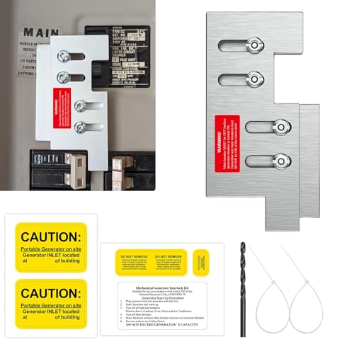
Compatible Models: Fit the Eaton or Cutler Hammer Vertical Throw CH Series CH-5 150 or 200 amp panels