
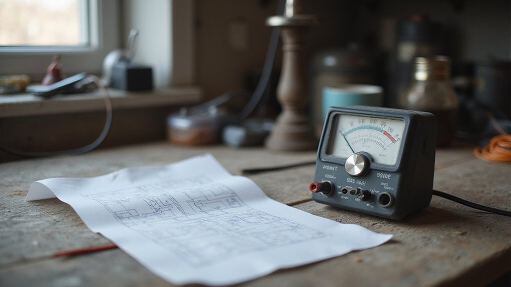

Ever wondered how to safely take measurements with a basic multimeter?
Knowing how to connect the probes and set the right mode can make all the difference between an accurate reading and a costly mistake.
By the end, you’ll understand the key steps to use a non-digital multimeter confidently and avoid common pitfalls.
Everything you need is right here to get started.
Why Still Use an Analog Multimeter?
You still use an analog multimeter because it offers critical advantages for certain tasks. The moving needle provides precise insights for diagnosing vintage electronics, where digital displays might miss subtle details. Observing the needle’s continuous movement allows you to perform visual signal analysis, revealing gradual changes, drops, or drifts in a circuit instantly. This real-time feedback helps you spot trends and fluctuations quickly, making tuning and peak adjustments more efficient. For those seeking top battery picks, analog multimeters also excel in fine-tuning applications by showing minimum and maximum readings during iterative adjustments. Their simplicity means you don’t rely on batteries for basic voltage and current measurements, which enhances reliability during extended fieldwork. Additionally, their straightforward design results in lower cost, easier maintenance, and no internal noise or delays caused by digital sampling. In environments with electrical interference, analog meters often provide clearer, more stable readings, making them an invaluable tool in specific contexts. For measuring DC output from modern MC4 connectors, analog multimeters offer immediate visual feedback on panel performance trends. By monitoring gradual voltage drops, you can spot early signs of ageing in a battery before it fails completely.

High accuracy & Ideal for AC and DC Voltage DC Current up to 10A

Analog Multimeter - Multitester

Made of high quality materials, practical.
Set Up Analog Multimeter Probes Correctly
To set up your analog multimeter probes correctly, begin by performing jack identification. Insert the black lead into the COM terminal, which is usually marked with a “–” or an asterisk. The red lead should be plugged into the V/Ω/mA terminal for testing voltage and resistance; some meters label this jack with a “+” instead. Always double-check that the labels match your intended function—don’t rely on memory or guesswork. For current measurements, use a separate red jack designated for current testing, never the voltage port. Fully seat each probe into its terminal to prevent loose connections, which can cause unstable readings or damage the meter. Confirm your setup before touching the circuit to ensure accuracy and protect both the meter and yourself. However, note that a battery backup option is essential for powering your analog multimeter during a home outage.
Select the Right Mode and Range for Your Test
To select the right mode and range for your test, start by setting your rotary selector to the appropriate function: DCV for direct-current voltage, ACV for alternating-current voltage, or Ω for resistance. Choosing the correct mode ensures your meter routes signals through the proper internal circuitry, which is essential for accurate readings. Next, match the range to your estimated value—select a range slightly above the expected measurement. For voltage tests, pick a range higher than the circuit’s voltage to prevent overload; for resistance measurements, choose a multiplier such as ×100 or ×1K to get a precise reading. Always consider the health of the batteries before testing, as weak batteries can distort resistance readings. Regular calibration of your meter helps maintain accuracy by compensating for any drift or internal changes over time. Verify that you are reading the correct scale; for example, if you set the meter to 10 V but are testing a 10 V circuit, use the 0–10 V scale—not the 50 V scale—since small misreads can lead to significant errors. Additionally, be aware that simple habits like proper storage can add years to your meter’s functional life, just as they do for portable power stations. For instance, avoiding exposure to extreme heat and moisture helps prevent premature component degradation that shortens device lifespan. Following the same principle, using the safest fix order helps protect delicate components from damage during maintenance.
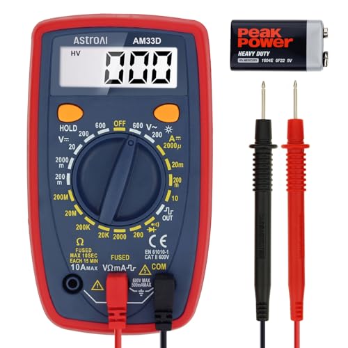
Additional Tips - The following incorrect operations may cause the multimeter not to show results: Firstly, the plugs of test leads are not fully inserted or not inserted into the correct sockets. Secondly, the manual rotary switch is not placed in the correct position. In addition, this meter can not test all AC Current and below 100mV AC Voltage. Please check the user manual carefully before measurement.
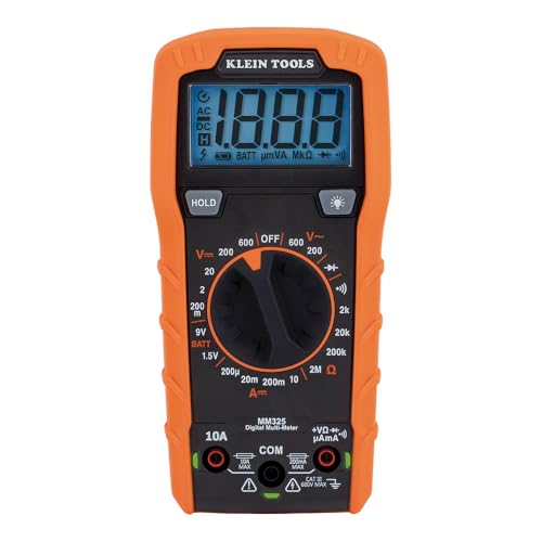
VERSATILE FUNCTIONALITY: Measures AC/DC voltage up to 600V, 10A DC current, 2MΩ resistance; additional features include continuity, diode test and battery test

Accurately Test Full Features: Accurately measures AC/DC voltage, DC current, resistance, continuity test, diode and batteries.
Start With the Highest Range to Protect Your Meter
Start with the highest voltage or resistance range on your meter. This approach ensures range safety and prevents overload by protecting the meter’s movement from full-scale deflection. Using a low range initially can cause the needle to peg instantly, risking damage and inaccurate readings. Always begin at the highest setting, then systematically step downward until the needle lands in the upper half of the scale. This technique provides a safe, approximate value first, which you can then refine for better resolution. If the needle barely moves on the high range, you’re safe. If it pegs, return immediately to the highest range. Never guess; start high and narrow down progressively for precise measurement. For a more reliable measurement, you can also reference the quality and performance of top inverter and battery charger combos to cross-check your readings against known standards. This same principle of starting with the highest range prevents accidental short circuits, which is why negative battery cables come off first when working with batteries. If your circuit repeatedly causes the needle to peg, it may indicate an overload or short circuit that is also tripping your breaker box.

Versatile Digital Multimeter - Accurately measures AC/DC Current, AC/DC Voltage, Capacitance, Frequency, Duty Cycle, Resistance, Diode, Continuity and Temperature.

CAT III 600V Safety Rating: Ensuring your safety when working on electrical systems in common residential, commercial, and industrial settings.

HIGHER RESOLUTION & ADVANCED DESIGN: 20000 counts, HT118E multimeter with more resolution bits allows for more accurate measurement results. The flashlight on the back ensures easy use in dimly lit places. Min/Max to record signal fluctuations. Stable kickstand, Pen slot on the back, Low battery prompt, Data retention, Auto power-off
Read the Needle and Scale Without Parallax Errors
To avoid parallax error when reading a meter, you must align your line of sight directly perpendicular to the dial. Parallax can cause a misreading of a full division or more if you don’t correct for it. To do this, position your eye so it is directly in front of the needle. Then, shift your head until the needle and its reflection in the built-in mirror overlap perfectly. Proper mirror alignment is confirmed when the reflection disappears directly beneath the pointer, not beside it. If you see a double image, your angle isn’t correct; readjust and verify before taking the measurement. Only record the value once you see the overlap clearly. Use the scale that matches your measurement range, and estimate between marks if necessary. Even a gentle tap on the meter face can help reduce friction effects before reading. Being systematic with this process prevents dangerous mistakes caused by misreading. Take your time, tilt your head slightly if needed, verify the alignment, and lock in the measurement before proceeding.
Zero the Ohm Scale Before Measuring Resistance
Before measuring resistance, zero the ohm scale to ensure accurate readings. Begin by selecting an appropriate ohms range, such as R×1 or R×100. Next, firmly short the metal probe tips together, creating a direct short circuit. Turn the zero-ohms adjust knob until the needle points exactly to zero ohms on the far right of the scale. This step compensates for lead resistance and ensures the meter provides true readings. Unlike AGM batteries, which rely on absorbed glass mat technology to hold electrolyte, your meter’s internal battery powers the test circuit, so its condition directly affects zeroing. For reliable measurements, always use a circuit breaker box that meets your home’s load requirements. For a clean finish after removing ties, use flush cutters to trim excess tails flush against the head.
Repeat this zeroing process before each measurement session and whenever you change ranges. If the needle refuses to reach zero, check your internal battery— a weak battery can prevent proper zeroing. Also, examine your test leads for dirt or damage because dirty probes or loose contacts can mimic resistance and throw off the zero setting. After zeroing, keep the same range setting for your measurements to maintain consistency. Remember, in the ohms scale, zero is located on the right, while infinity is on the left; proper zeroing is critical for accurate measurement.
Common Analog Multimeter Mistakes and How to Avoid Them
Always verify you are on the correct range before taking a measurement. Selecting the wrong range can cause the needle to peg at either extreme, providing an unhelpful or misleading reading. When measuring unknown values, start with the highest range to prevent overload and damage to the meter. Before each test, check your jack placements carefully. Using the wrong jack for current versus voltage measurements can short your circuit or damage the meter. Never attempt to measure resistance on an energized circuit; doing so risks burning out the meter movement. Calibration is crucial—if the needle does not rest at zero after turning the calibration screw, adjust it until it does. Always read the scale directly in front of the needle to avoid parallax errors, which can skew your readings. Confirm that the DC polarity is correct; reversing the leads will deflect the needle backward, leading to incorrect readings. If your meter behaves erratically, inspect for a blown fuse or loose internal connections, as these issues commonly cause inconsistent measurements. For accurate DC power monitoring in your system, pairing your meter with a high-quality solar inverter ensures reliable performance. For solar installations, you should also choose top solar panels for farming rated to withstand outdoor conditions. DIY solar panel projects require similarly careful meter handling to avoid shorting a live photovoltaic array.