
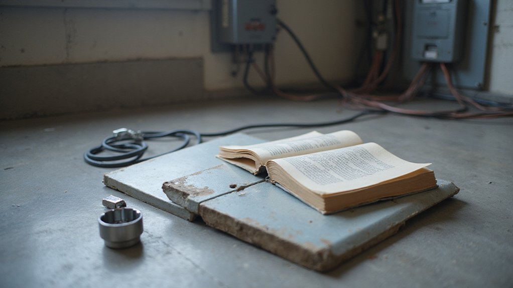

Ever wondered how to safely connect a new breaker in your breaker box? Getting it right is crucial for safety and code compliance.
By the end, you’ll know the exact steps to install a breaker properly, from turning off power to securing all connections.
Keep reading for a straightforward guide to wiring your breaker the right way.
Tools You Must Have for Breaker Installation
To install a breaker safely and correctly, you need a set of essential tools. Insulated screwdrivers—both flathead and Phillips—are crucial for tightening terminal screws without risking shock. A square-drive (Robertson) bit may also be necessary for specific panel fasteners. Wire strippers are necessary for cleanly preparing conductors, and insulated needle-nose pliers help with routing wires in confined spaces.
Personal protective equipment (PPE) is non-negotiable: wear safety goggles to shield your eyes and insulated gloves to protect against shocks. Use a torque screwdriver to tighten lugs precisely according to manufacturer specifications. A voltage tester or a non-contact tester allows you to verify that the circuit is de-energized before working. For poorly lit panels, a headlamp provides extra illumination. Lastly, lineman’s pliers are useful for shaping conductors securely. With these tools on hand, your breaker installation will meet safety standards and code requirements, and just as solar farm layouts require careful planning of panel spacing to maximize sunlight exposure, your breaker box wiring demands deliberate attention to torque settings and wire routing for optimal performance. Similarly, comparing the best costs for solar panels helps homeowners evaluate their return on investment before committing to a large electrical project. For overall system reliability, selecting reliable power inverters is just as critical as properly wiring your breakers.

INSULATED SCREWDRIVER SET: Includes 4-Inch round shanks in a #2 Square, #2 Phillips and 1/4-Inch Slotted tips (Cat. Nos. 6844INS, 6834INS, 6824INS)

10-IN-2 INSULATED MULTI-BIT AND MULTI-BIT PRECISION SCREWDRIVER SET: Includes a #00, #0, #1, and #2 Phillips tip, 3/32, 1/8, 3/16, and 1/4-Inch slotted tips, and a #1 and #2 square tip for versatile applications

Interchangeable Insulated Screwdriver Set with an insulated handle, 5 interchangeable insulated blades, and a carrying pouch
How to Shut Off Power and Verify Zero Voltage
To shut off power and verify zero voltage, start by turning off the circuit breaker using its normal control—usually a switch or handle. Then open the disconnecting device and move the breaker handle fully OFF to ensure the circuit is de-energized. Identify all sources feeding the equipment, including any and all alternate feeds or backfeed paths, and apply lockout/tagout devices to prevent accidental re-energization. Knowing the breaker box location in advance helps you act quickly in an emergency.
Never assume that an OFF breaker indicates a dead circuit. Mislabeling panels and backfeed situations can leave parts energized even when the breaker is off. To confirm the circuit is truly de-energized, perform voltage testing at the work location with a properly rated and verified multimeter. Use the live-dead-live testing sequence: first test on a known live source to confirm the meter’s accuracy, then check each phase-to-phase and phase-to-ground points to verify zero voltage, and finally retest on a known live source. This approach ensures reliable circuit confirmation. Additionally, check for residual or induced energy by grounding phase conductors as necessary. Keep the panel treated as energized until you’ve completed the full verification process. Applying this same principle to battery work, it is standard practice to remove the negative cable first to prevent short circuits. When selecting a battery for your system, refer to reviews that compare top battery picks based on quality, performance, and value.
Removing the Dead Front Safely
You need to remove the dead front to access the breaker terminals and bus bars for wiring or inspection. Before beginning, gear up with safety glasses and insulated gloves. Ensure you have dry footing and use insulated tools to prevent shock hazards.
Start by locating the retention screws, and use only the original blunt-tip hardware to avoid puncturing wires behind the cover. Support the dead front securely while removing these screws in a controlled, logical sequence. Lift it straight off, being careful not to scrape or damage any insulation. Never drop the dead front onto live parts—doing so can cause damage or create a safety hazard.
Once removed, assume all exposed bus bars and connections are live. Never leave the open panel unattended. If you need to temporarily block access, install a blank cover or barrier. Before restoring power, reinstall the dead front securely with all original screws. Failing to replace or damaging the dead front creates a code violation and significantly increases the risk of shock. Similar safety precautions apply when you need to perform a hard reset on a SolarEdge inverter, as residual voltage can remain in the system. Consider that fuse blocks, by contrast, use a different method for circuit protection and typically require a separate pull-out disconnect for servicing. For example, an AGM battery following proper charging habits can also have its usable lifespan extended well beyond typical expectations.
Routing Cable and Stripping Wires Correctly
To route and strip wires correctly, start by mapping the cable’s path from the destination back to the panel. Choose the shortest practical route that avoids studs, plumbing, or existing wiring. Use drilled holes or approved conduit pathways where framing interrupts a direct run. Keep cable management orderly to improve serviceability and reduce crowding, making future adjustments easier. Using a digital clamp meter can help verify that circuits are de-energized before beginning this work. For gel batteries, similar careful handling applies when using a specialized charger profile to avoid overcharging and damage.
When the cable reaches the panel, bring it through a proper knockout with a matching connector. Insert the cable securely and leave a short portion of jacketed cable inside the enclosure before sheathing removal. Use a cable ripper to carefully open the outer sheathing, ensuring you avoid deep cuts that could damage the conductor insulation. Only strip the sheath as much as necessary for the terminal connection.
Strip each conductor to the length specified by the terminal, usually between 8 and 10 millimeters for screw-clamp terminals. Use a wire stripper properly sized to the cable gauge to prevent nicking or damaging the conductor. After stripping, arrange the conductors with smooth bends, keeping hot, neutral, and ground wires separated. Confirm that the stripped ends are clean and free of deformation before making your connection. A failed breaker can compromise the breaker box range, potentially leading to overloads or fire hazards.

OUTER JACKETING SLITTING: Cable ripper effortlessly slits and trims outer jacketing on 12/2 and 14/2 NM cable in one smooth operation

✅ 8 inch Professional Wire Stripper: Cuts, strips wire and loops 10-22 AWG Solid copper wire or aluminum cables.high carbon alloy steel with accurate stripping.

Slits outer covering of all sizes, both old and new, non-metallic (type NM) sheathed cable
Choosing the Right Breaker: Single-Pole or Double-Pole
To determine the appropriate breaker type, start by checking the circuit’s voltage. For 120-volt circuits, use a single-pole breaker, which controls one hot conductor and is suitable for lighting, outlets, and small appliances. These breakers typically range from 15 to 20 amps. For 240-volt circuits, a double-pole breaker is necessary. It controls two hot conductors simultaneously through a mechanically linked handle, ensuring both poles trip together. This setup is ideal for high-demand appliances like dryers, ranges, and electric vehicle chargers, with common ratings from 20 to 60 amps. For DIY projects, DIY cable ties can help organize wiring during installation. To verify proper operation after installation, use a multimeter set to AC voltage to test for correct readings like 120V or 240V between the breaker’s terminal and the neutral bus. When selecting a new panel, look for a breaker box that offers clear labeling and ample space for future circuits.
Matching the breaker type to the circuit voltage is essential for safety and compliance. A single-pole breaker should never be used on a 240-volt line, as this creates a serious safety hazard and violates electrical codes. Check your panel’s configuration because double-pole breakers occupy two adjacent spaces and support balanced loads across both service legs. Ensuring proper compatibility helps prevent electrical hazards and maintains proper system function.

Single pole, 15 Amp, 120V type QP Circuit Breaker

RELIABLE CIRCUIT PROTECTION: Designed as a 15 amp circuit breaker, this unit offers dependable protection for residential and light commercial electrical systems. Prevents overloads and short circuits.
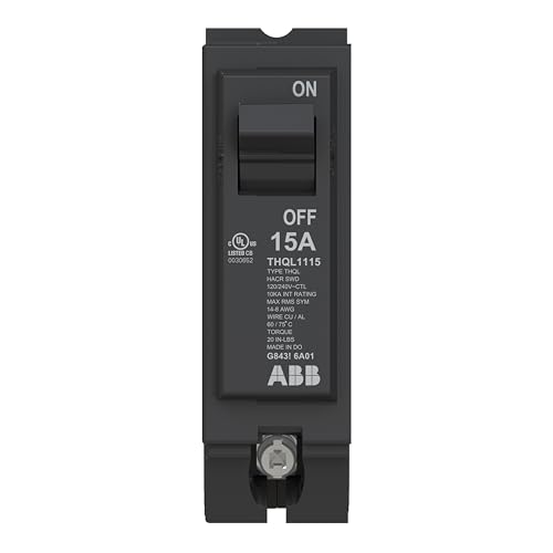
POWER PROTECTION - This thermal magnetic circuit breaker provides protection for residential and commercial electrical systems. ABB's 15A single-pole breaker protects again electrical faults to enhance safety.
Step-by-Step: Installing and Connecting the Breaker
After de-energizing the panel and confirming the circuit is dead, you will start by removing the appropriate knockout for the new cable and installing a listed cable clamp. Ensure the clamp fits tightly to prevent movement or strain on the cable. Route the cable through the clamp, leaving enough length to make clean, secure terminations on the circuit wires. Use wire strippers to remove the insulation from each conductor, matching the manufacturer’s recommended length—usually about 1/4 inch—to ensure proper connection without risk of short circuits. Firmly attach each wire under the corresponding terminal screw on the breaker, tightening securely to prevent loose connections that could cause overheating. Be cautious of live main lugs and the main line even when the breaker is off to avoid shock hazards.
Verify that the breaker size matches your circuit load—using the specified amperage—and confirm that the panel is compatible with the breaker type before seating it. Align the breaker with the bus bar, then push it in firmly until the rear clips lock into place. Check that the breaker sits securely and engages properly. Reinstall the dead-front cover onto the panel, ensuring that any DIY breaker box cover modifications are compatible with safety requirements. Before restoring power, double-check that all connections are tight and the panel is properly closed. Turn on the main power supply and test the circuit carefully, watching for signs of trouble such as unusual heat, tripping, or sparks. If required by local code, schedule an inspection to ensure everything is installed correctly and safely. To maximize the lifespan of a battery-powered system, you should also apply correct voltage limits when charging a deep-cycle battery to prevent overcharging and sulfation. When securing the new cable, consider using removable cable ties for temporary management during installation to keep wires organized and out of the way.

Package Contents: The package includes 4 pcs 1/2 inch clamp cable connector and 1 pcs screwdriver, sufficient quantity to meet your daily use and replacement needs. Size: 1/2 inch. (Please confirm the size before purchasing.)

These Metallic Connectors are made of steel with zinc coating are cable connectors for Romex wire

Package Included: You will get 6 pieces 1/2" Type Clamps and a dual head dual purpose screwdriver.
Where Neutral and Ground Wires Go (and Why It Matters)
In a subpanel, the neutral and ground buses must remain separate. The neutral bus carries return current during normal operation, so its conductors—typically white wires—must be connected to the neutral bus. The grounding bus, which is connected to bare copper or green wires, provides a low-impedance fault path that directs potential fault current safely to ground. If these buses are bonded together in a subpanel, it creates a continuous path for current along grounding conductors, increasing the risk of shock and interfering with proper breaker operation. This is why proper bonding is only allowed at the first disconnect point, such as the main panel, where the neutral and ground are intentionally linked to ensure a low-resistance fault path back to the source. Many modern systems also use string inverters to efficiently convert DC power from solar panels into AC for home use. For residential installations, understanding the different best use cases for neutral versus ground in the breaker box helps ensure code compliance and maximum system durability. Therefore, always keep the neutral and ground buses isolated in a subpanel to ensure that fault current follows its intended path and safety is maintained.
Checking Your Work Before Closing the Panel
After turning off the main breaker and confirming zero voltage with a calibrated tester, conduct a detailed pre-close inspection. Begin with your grounding procedures: ensure all terminations are torqued to manufacturer specifications, that no insulation is trapped under clamps, and that conductors are fully inserted. Next, follow your inspection checklist systematically: verify each breaker is fully seated and not wobbling, and that it matches the panel’s listed specifications. Look for signs of overheating such as scorch marks, melted plastic, or burnt odors. Confirm the breaker amperage ratings are appropriate for the wire sizes used. Make sure all unused openings are covered with proper blank covers. Additionally, verify that all hot wires are correctly connected only to their breakers and that safety breakers with white neutral pigtails are properly connected to the neutral bus bar when used. Finally, perform a visual scan to identify any exposed energized parts or visible defects. Skipping these steps can compromise safety and code compliance, so meticulous thoroughness is essential before closing the panel.
Final Steps: Labeling, Covering, and Restoring Power
Label each circuit precisely in the panel directory, noting its specific purpose such as “kitchen outlets” or “living room lights.” Ensure the labels are positioned so they do not block or obscure the breaker handles. Keep the directory clear and organized, matching circuit numbers to room names and updating it promptly whenever changes are made. This practice allows for quick, accurate identification during emergencies or troubleshooting.
Reinstall the panel cover securely. Confirm the deadfront is seated properly, with no wires pinched or exposed. Use all the original screws to fasten the cover tightly, ensuring it remains closed and protects against accidental contact with live parts.
Finally, restore power carefully. Turn on the main breaker only after the cover is securely in place. Then, energize the circuits one at a time, watching vigilantly for buzzing sounds, excessive heat, or sparks. If any circuit shows signs of damage or a breaker fails to stay on, shut everything down immediately and contact a professional electrician.

Perfect Fit & Compatibility: Designed as direct replacements for lost or damaged screws, these panel screws ensure a secure fit for Schneider Electric QO & Homeline, Siemens, and Murray load centers and breaker boxes.

Replaces lost or damaged load center cover and service entrance device screws

Screws Size: Each electrical box screws is 0.8 inches long, matching most distribution box configurations. It ensures a perfect fit with standard cabinet equipment, providing a tight and secure fixation, keeping your equipment securely in place