
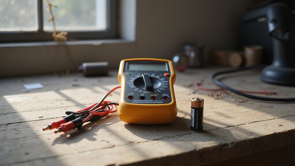

Ever wonder how to safely and accurately test electronics with a multimeter? If you’re just starting out, knowing the basics can seem daunting, but with the right steps, you’ll be measuring voltage, resistance, and continuity like a pro.
By the end of this, you’ll understand how to set up your multimeter and take your first readings confidently. The full guide below will walk you through each step.
What a Digital Multimeter Measures and Why You Need One
A digital multimeter provides precise measurements of voltage, current, and resistance in electrical circuits. These values are crucial because they reveal the actual state of the circuit, such as whether it’s powered correctly or if there’s a fault. Without a multimeter, you’re left guessing about the invisible electrical behavior happening inside wiring and components. To maximize the lifespan of your testing equipment, simple habits like proper storage and avoiding over-voltage ranges can add years to its accuracy. For reliable field testing, consider pairing your multimeter with a top power bank that includes a wall outlet for continuous device operation.
Earlier tools like the VOM (volt-ohm-milliammeter) were bulky, analog devices that relied on needle movement to indicate readings. While useful, they limited accuracy and required interpretation, which could lead to errors. The digital multimeter revolutionized this process by offering clear, numeric displays that deliver exact figures, making measurements faster and more reliable.
You use it to verify Ohm’s law by checking how voltage, current, and resistance relate; test power supplies for stability; and identify faults or broken connections within the circuit. Essentially, it transforms unknown electrical conditions into concrete data, enabling you to diagnose issues efficiently. The digital multimeter acts as your essential tool for bridging theory with practical circuit health assessment. For sourcing power, pairing it with top battery picks ensures accurate testing of the battery’s terminal voltage under load.
Check Your Digital Multimeter’s Battery and Leads First
Begin by powering on your digital multimeter and checking for a low-battery indicator on the display. If the indicator appears, replace the battery immediately to ensure accurate readings and reduce the risk of shock. Confirm that the display lights up without flickering or dimming and that the battery compartment closes securely.
Next, inspect the leads thoroughly. Look along the entire length of both leads for cracks, cuts, or exposed conductor material. Run your fingers over the insulation to feel for nicks, thinning, or damage, especially near the probe tips and banana plugs. Check that the probe tips are clean, straight, and free of corrosion. Ensure the banana plugs seat firmly into the meter without wobbling. Damaged wires against hot surfaces can cause internal damage that is not obvious from visual flaws. Always observe proper safety precautions when handling leads near live circuits. Understanding the display’s numeric value helps distinguish normal power usage from faulty draw. For disconnect switch applications, selecting the right fuses is essential to prevent overcurrent damage.
Finally, test the continuity of each lead. Touch the probe tips together and expect a reading under 0.5 ohms. Wiggle the leads during this test to check for intermittent breaks. If any lead fails the visual inspection or the continuity test, replace it before proceeding.
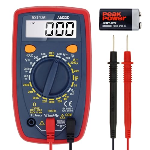
Additional Tips - The following incorrect operations may cause the multimeter not to show results: Firstly, the plugs of test leads are not fully inserted or not inserted into the correct sockets. Secondly, the manual rotary switch is not placed in the correct position. In addition, this meter can not test all AC Current and below 100mV AC Voltage. Please check the user manual carefully before measurement.

Accurately Test Full Features: Accurately measures AC/DC voltage, DC current, resistance, continuity test, diode and batteries.
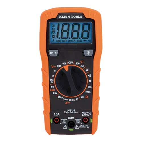
VERSATILE FUNCTIONALITY: Measures AC/DC voltage up to 600V, 10A DC current, 2MΩ resistance; additional features include continuity, diode test and battery test
How to Plug In Test Leads the Right Way (Without a Blown Fuse)
Plugging in test leads correctly is essential to avoid blowing a fuse. First, always insert the black lead into the COM jack—no exceptions. This serves as your fixed reference point. The red lead placement depends on what you are measuring. For voltage, resistance, or continuity, insert the red lead into the VΩmA jack. Avoid plugging the red lead into the 10A jack unless measuring high current; doing so while testing voltage can cause your fuse to blow. Always check that your meter is compatible with the same MC4 connectors found on top-rated solar panels. For reliable power transfer during generator testing, consider familiarizing yourself with automatic transfer switches to ensure safe switching between sources. Selecting a meter with a battery tray secure enough for long-term storage is also important for maintaining reliable readings.
Before moving leads between jacks, turn your meter off. Always insert the black lead first, followed by the red into the appropriate jack for your measurement. Check the jack labels on your specific meter model—they vary, but never assume. This deliberate sequence is critical for fuse safety. Skipping steps or rushing can lead to blown fuses and costly replacements.

42-STRAND COPPER MULTIMETER LEADS: Each multimeter lead uses a 42-strand copper conductor to support stable signal transmission and currents up to 10A. Internal nylon reinforcement helps reduce conductor strain when these multimeter test leads are bent repeatedly during routine electrical measurements.

Patented TwistGuard extendable tip shroud meets the highest electrical safety requirements to reduce tip exposure while providing the versatility needed for most measurements

UNIVERSAL COMPATIBILITY: Standard banana-type inputs compatible with most multimeters and clamp meters
How to Set Your Digital Multimeter’s Dial for Voltage, Resistance, or Continuity
To set your digital multimeter’s dial correctly, always match the selector to the measurement you plan to take. For measuring voltage, choose V—a straight line for DC voltage or a wavy line for AC voltage. Turn the dial to the appropriate range, preferably the highest available for initial testing, then switch to a lower range for more precise readings. For resistance, select Ω and set the lowest practical range on manual meters to prevent overload readings that could damage the meter or give false results. To test continuity, choose the symbol resembling a sound wave or a diode; first, test the leads together to ensure the beep function works. Confirm that the display matches the selected mode before proceeding with measurements. For consistent accuracy over time, note your meter’s calibration schedule and perform routine maintenance: store it dry, replace the battery when the display dims, and keep the test leads in good condition. Always set the dial correctly before taking any measurement to ensure reliable and safe results. Never fail to wear proper safety equipment before using the multimeter, as emphasized in the manufacturer’s safety protocols.
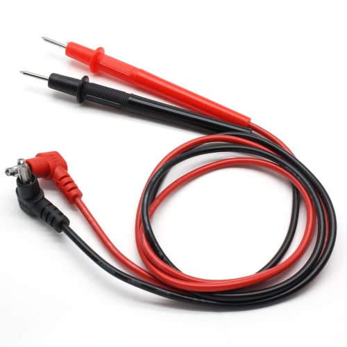
🥇What You Will Get: 1 Pair Multimeter Replacement Leads, it is a useful tool that will bring a lot of convenience to your electronics work
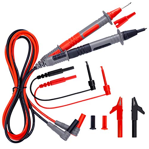
SECURITY LEVEL AND HEAVY DUTY - It is safe to test CAT III 1000V &CAT IV 600V rated current 10A current, perfectly fits all kinds of multimeters like clamp meters, digital multimeters, table meters

[Great value, full set] our test lead set comes with two additional professional alligator clips (Alligator Clips). This means you can achieve "hands-free" convenient operation without paying extra. It is very suitable for long-term voltage monitoring or connecting hard-to-reach test points. The cost-effectiveness is obvious at a glance.
Measure AC and DC Voltage Safely With Your Digital Multimeter
To measure AC and DC voltage safely with your digital multimeter, start by inspecting the meter and leads for damaged insulation—this is crucial for accurate readings and safety. Insert the black lead into the COM port and the red lead into the V port; avoid using a current port to prevent creating an arc-flash hazard. For AC voltage measurements, select the wavy-line symbol, begin on the highest range, and then step down to lower ranges as needed. For DC voltage, choose the straight-line symbol, connect the red lead to the positive terminal and the black to the negative, and hold the probes steady until the display stabilizes. Understanding the working principle of a power meter helps clarify how your multimeter converts electrical current into a usable measurement. When connecting to a battery, always follow the correct wiring order to avoid dangerous sparks or short circuits. For deep cycle batteries, matching the charger size to the battery’s amp-hour rating is key to optimizing charge time and preventing damage.
Always keep your fingers behind the probe guards to minimize the risk of electric shock. Treat any voltage above 35 volts DC or 25 volts AC RMS as a potential shock hazard. Avoid measuring circuits with switching surges, such as motors, because they can damage your meter. When troubleshooting errors or uncertain readings, first de-energize the circuit and then verify the presence of voltage. After each measurement, disconnect the probes to prevent accidental contact or damage.

2mm/0.07" probe tip ,90cm / 35" total length, banana Connector.

Important Tips - This CM2K0R clamp meter can not test DC Current. To measure the AC Current you need to clamp the meter around one of the wires and not the whole power cord. Ensure the conductor to betested is in the center of the clamp head. The clamp Jaw is only used to measure current. Do not measure voltage by clamping the conductor being measured.
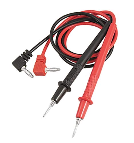
1000V voltage , 80cm length, 2mm probe tip with 4 mm screw teeth, 4mm diameter banana plug
Test Resistance and Continuity (Power Must Be Off)
Before testing resistance or continuity, ensure all power is turned off and the circuit is de-energized. Confirm zero voltage with your meter to verify safety. Disconnect the component from its power source completely, including removing batteries or unplugging. Isolating the circuit prevents false readings and potential damage. Remember that the circuit must be de-energized because voltage can confuse resistance readings. Unlike bifacial solar panels, which can generate power from both sides, standard testing components require a completely passive circuit to avoid interference. Locating your apartment’s breaker box is a key first step to safely isolating a circuit before testing. To ensure accurate results, always apply the exact test steps for measuring ohms as outlined in reliable multimeter guides.
Insert the black probe into the COM port and the red probe into the V/Ω port. Set the meter to continuity mode (speaker symbol) or, if unavailable, the lowest resistance (Ω) range. Touch the probes together; a beep confirms the setup is correct.
To test continuity, connect the probes to both ends of a wire or fuse. A beep and a near-zero ohm reading indicate a closed connection. No beep or an OL reading suggests an open circuit. When measuring resistance, place the probes across a disconnected component. A low resistance indicates current flow, while OL usually means a break. Always compare your readings to a known good connection for accuracy.
How to Measure Current With Your Digital Multimeter
First, physically break the circuit path at your measurement point. Connect one meter lead to each open circuit end, completing the loop in series. Make sure the meter is inline, not across any component, to properly measure current. Once the series connection is secure, restore power carefully. Read the displayed current value on the multimeter. For more accurate readings, check if your meter requires prior calibration against a known current source. Ensure the red test probe is inserted into the appropriate current socket based on the expected current range. A quality lithium battery charger can also benefit from this measurement to verify its output current. Using a properly crimped terminal ensures a reliable connection for these test leads. After recording the measurement, disconnect the power, remove the meter, and reconnect the circuit to its original configuration. Monitoring current draw helps prevent premature capacity loss in your solar generator.


COMPLETE MULTIMETER KIT: Manual-ranging digital multimeter with heavy-duty carrying case for organized storage and protection of testing equipment

Versatile Digital Multimeter - Accurately measures AC/DC Current, AC/DC Voltage, Capacitance, Frequency, Duty Cycle, Resistance, Diode, Continuity and Temperature.
Read the Display: What a Negative Sign or Steady Beep Means
A negative sign on your digital multimeter indicates that the probes are connected with reversed polarity during DC voltage measurement. This isn’t a fault but a signal that the positive and negative leads are swapped. While the reading shows the correct magnitude, the negative sign helps you identify the correct orientation of your probes. Use this information to troubleshoot circuit connections and ensure proper color coding when testing battery terminals. Understanding this polarity reversal is similar to the safety principle of disconnecting negative battery cables first to prevent accidental shorts. In a similar way, checking for proper polarity is critical when testing the output of a DIY solar panel before connecting it to a charge controller.
A steady beep in continuity mode confirms there is a complete circuit with low resistance, usually below 30 to 50 ohms. This beeping acts as a quick “go/no-go” indicator rather than a precise resistance measurement. It only signals that the circuit is closed, not that the connection is perfect. During troubleshooting, interpret the beep along with the resistance value displayed. Relying solely on the audio can lead to missing borderline or weak connections. Always verify correct probe placement and circuit condition before making conclusions.
What to Do If Your Digital Multimeter Reading Looks Wrong
If your digital multimeter reading looks wrong, the first step is to verify that you’ve selected the correct range and mode on your meter. Using the wrong setting, such as confusing AC with DC or measuring resistance when the circuit is powered, leads to false readings. Cross-check your results on a known good source to determine whether the issue stems from your setup or the meter itself. For example, a digital multimeter’s weak test signals in resistance mode may show high mega ohms despite an internal short, so using diode mode or an analog meter can reveal the true fault.
How to Store Your Digital Multimeter for the Next Use
To store your digital multimeter properly for the next use, follow these steps to ensure its longevity and safety. First, always power down and disconnect your meter before storing. Turn the dial to OFF and remove all test leads. Coil the leads loosely to prevent strain on the wires and connectors. Never leave the dial set to resistance or current ranges during storage, as this can affect internal components.
For battery safety, remove the batteries if you plan to store the meter for an extended period. This prevents leakage and corrosion at the contacts. Store the batteries separately in a dry place and reinstall them only when you’re ready to use the multimeter again, making sure to observe the correct polarity. Check the battery compartment for any residue or corrosion before reinserting the batteries.
Choose a dry, protected storage location away from humidity, direct sunlight, and extreme temperatures. A protective case is recommended; adding silica gel packets can help control humidity if needed. Keep the storage environment within typical ranges, usually below 50 degrees Celsius with humidity under 85 percent. Before bringing the multimeter back into service, inspect it thoroughly. Check the case, jacks, and leads for damage, and wipe down the case with a soft cloth for cleanliness and maintenance.