

Have you ever wondered what keeps you safe from electrical shocks and fires? That’s where a grounding wire comes in—it’s a vital part of your electrical system that stays inactive until a fault happens.
When trouble strikes, it provides a quick, low-resistance path straight into the ground, helping protect you and your home.
Keep reading to see how it works and how to spot issues with your grounding system.
What Is a Grounding Wire vs. Hot and Neutral?
The grounding wire, typically bare copper or green, does not carry current during normal operation. Instead, its primary purpose is to provide a safety path for electrical faults. Unlike the hot wire, which supplies power from the source to the load, and the neutral wire, which completes the circuit by returning current, the ground wire remains inactive unless a fault occurs. This stability is supported by ground rods buried outside to dissipate static electricity and high voltages. During a fault, such as a short circuit or a short in an appliance, the ground wire offers a low-resistance route for the fault current to flow safely to the earth. This helps protective devices like circuit breakers or fuses detect the abnormal current and trip, preventing electric shock or fire hazards. The ground wire ensures that when a fault happens, it causes the breaker to trip by creating a sudden surge that the protective device recognizes. When troubleshooting solar inverters, resetting the device may resolve minor ground fault issues, but persistent ground faults often require professional inspection of the DC wiring. The ground wire is an essential safety feature, ensuring that if something goes wrong, you and your equipment are protected by directing dangerous current away from contact points and harmlessly into the ground. You can quickly locate the breaker box, often called the main panel, in typical basement or garage areas of the home.
Why Does Your Home Need a Grounding Wire?
A grounding wire is essential for electrical safety in your home because it provides a reliable path for fault current to flow safely into the ground. When insulation fails or a metal part becomes energized, the grounding wire directs dangerous electricity away from exposed metal surfaces, reducing the risk of electric shock. It helps circuit breakers detect faults quickly and trip, preventing prolonged exposure to electrical faults. This process also limits the chance of overheating and sparking, which could lead to fires. Additionally, a proper grounding system works in tandem with overcurrent protection devices to ensure they activate as intended during electrical faults. This is similar to how removing the negative cable first prevents accidental sparks when working on a car battery. Because electrical codes require this safety feature, installing a grounding wire is a mandatory step to protect your home and its appliances from electrical hazards. A high-quality 100 amp breaker box ensures reliable fault detection and system performance. A generator interlock kit similarly ensures that backfeed power is safely routed through a dedicated breaker to prevent dangerous electrical conditions.

Used in load centers, CSED devices and NQOD and NF panel boards

This 1/2” diameter, 17.6” long ground rod is designed for durability and precision,ensuring easy compatibility with wires up to 12AWG solid or stranded.

COMPLETE GROUNDING KIT: Includes 1x 17.4-inch-long, 1/2-inch-diameter copper-clad steel ground rod and 1x 6.2ft 12 AWG grounding wire for a compact, ready-to-connect setup.
How a Grounding Wire Stops Electric Shocks
When a fault occurs, a grounding wire stops electric shocks by providing a low-impedance path for fault current to flow safely into the earth. This route, which has very low resistance, diverts stray current away from you and the energized metal parts. By bonding metal enclosures to the grounding conductor, touch voltages are kept near zero, reducing the risk and severity of shocks. The high fault current also causes circuit breakers or fuses to trip quickly, cutting off power and preventing further danger. To ensure this protection works, it is critical to check for proper connections in the breaker box when wiring a 220V circuit. While grounding effectively reduces shock risk, it is important to test the grounding system regularly because damaged or open ground wires can still leave metal parts energized and pose a shock hazard. Avoid common misconceptions, such as believing a ground wire always prevents shocks; proper maintenance and testing are essential for safety. A failed battery isolator similarly compromises system protection by interrupting the intended current path. This robust safety function is similar to how an analog multimeter offers a reliable, continuous deflection for tracking steady faults.
How a Grounding Wire Prevents Electrical Fires
A grounding wire prevents electrical fires by providing a low-resistance path for fault current to flow directly into the earth. This rapid diversion helps prevent overheating of wiring components like insulation, wood framing, or drywall, which are combustible materials. When a fault occurs, the grounding wire directs abnormal current away from these materials, reducing the risk of fire. Ensuring a solid, reliable connection enhances conductivity, allowing circuit breakers to trip faster and disconnect power quickly. If power is lost at the meter, checking the breaker tripped condition is a critical first step to restoring electricity safely. This minimizes sustained arcing and thermal stress, both of which can ignite fires. Without a proper grounding path, stray energy can accumulate on metal enclosures, leading to repeated heating events that increase fire risk. Grounding also supports the operation of protective devices by creating clear fault conditions. These devices depend on accurate fault detection to trip and shut off power immediately. In this way, grounding acts as a crucial safety layer, helping prevent electrical fires by controlling fault currents and reducing potential ignition sources. For optimal protection, choosing top battery picks with terminals ensures reliable connectivity and low-resistance paths for fault current diversion. A lithium battery charger with proper grounding further enhances safety by preventing stray voltage buildup during charging cycles.
What Happens Inside a Grounding Wire During a Short Circuit?
During a short circuit to grounded metal, the grounding wire, which normally remains inactive, suddenly becomes a low-resistance path for fault current. This causes an abrupt surge of high current that rises sharply because of the minimal resistance. The fault current can reach thousands of amps, limited only by the impedance of the path. As a result, the wire experiences intense heat due to rapid heating caused by the high current flow. The conductor’s short-circuit withstand rating determines whether it can survive this event; for example, a 10 AWG copper wire can typically handle around 4,300 amps for a single cycle. This quick spike in current rapidly triggers circuit protection devices like breakers or fuses, which interrupt the circuit within milliseconds. This process is similar to how an automatic changeover switch uses sensors to detect a fault and instantly transfer the load to a backup power source, ensuring continuous safe operation. Choosing the right interlock kit ensures that your generator’s connection to the panel meets safety codes and allows for proper fault handling. This fast response prevents the wire from overheating and keeps exposed metal at earth potential, reducing the risk of electric shock. For portable setups, ensuring your grounding system can handle such surges is critical, as solar panel integration often relies on robust power management to maintain stability during fault events.

Copper Steel Composite Material

BARE WIRE: 99.9% pure copper wire. 10 Gauge/2.6 mm 10 Feet 5 oz

✅ 8 inch Professional Wire Stripper: Cuts, strips wire and loops 10-22 AWG Solid copper wire or aluminum cables.high carbon alloy steel with accurate stripping.
Where Does the Ground Wire Connect? (Rods, Panels, and Earth)
The ground wire connects to the grounding bus bar in the main electrical panel, where equipment grounding conductors and the grounding electrode conductor are terminated. This bus bar is directly bonded to the panel’s metal enclosure with a main bonding jumper, such as a green screw or strap. The grounding electrode conductor, which connects to rods, metal panels, or other grounding electrodes (earth), also lands on this bus bar. In subpanels, the ground and neutral conductors are kept separate to prevent neutral current from flowing along grounding paths. All wire terminations must be tight and resistant to corrosion to ensure reliable electrical continuity and safety. To avoid the need for manual starting methods, such as pull cord repairs on portable equipment, some generators use an electric starter instead. A secondary clamp on a second grounding rod creates a continuous grounding pathway. For solar installations, panels with MC4 connectors ensure a secure and weatherproof connection to the grounding system. Before energizing a new circuit, a continuity test confirms the grounding path is intact and free of high-resistance faults, which a standard multimeter can perform accurately.

[Good Grounding Bar Kit] Providing an extremely sturdy and reliable structure for safe electrical installations; These neutral lugs are carefully designed to stand the test of time, providing an ideal solution for your wiring needs

11 small and 4 large terminal openings

GOUNENGNAIL branded Copper Ground Bar 1/4"(metric 6mm thick) x 2" (Metric 50mm wide) x 10" (metric 250mm long) with 1/4'' * 16 Terminal Positions. With SM40 polyester insulators made from UL material - QMFZ2.E252110,Rated Uimp up to 7.4kV.
Does a Grounding Wire Protect Against Power Surges?
A grounding wire does protect against power surges by providing a safe path for excess current to flow into the earth. During a surge, the wire redirects the added energy away from your devices, minimizing potential damage. Without a proper grounding connection, surge protection devices (SPDs) cannot operate effectively, as they rely on the ground to channel away the harmful voltage spike. Short, straight grounding conductors improve this diversion process, enhancing the overall protection. Pairing your surge protector with a solid grounding wire ensures that surges are safely diverted, reducing risks to your equipment. To verify that this path is intact, you can test your breaker box with a multimeter set to measure resistance between the ground bar and a known earth reference. Selecting a top power inverter that includes robust grounding specifications further ensures your system can handle surge energy safely.
5 Warning Signs Your Grounding Wire Has Failed
Visible signs of corrosion or damaged insulation on the ground wire are key indicators that your grounding system may have failed. Corrosion, especially at connection points, can cause poor conductivity, leading to unstable grounding. Damaged insulation exposes the wire to moisture and contaminants, which accelerates corrosion and increases the risk of electrical faults. These visual clues often result in intermittent equipment malfunctions, erratic electronic behavior, or repeated hardware failures. If you notice these issues, it’s crucial to have a qualified electrician inspect and repair the grounding system immediately to prevent potential hazards.

Secure Bond: One-piece tinned copper barrel locks wires securely with minimal voltage drop and high current flow, preventing short circuits on every joint; Corrosion-resistant crimp connectors with heat shrink tubing deliver reliable, long-lasting performance

PetsTEK Wire Splice Kit for Electric In-Ground Dog Fence Systems. Compatible with All PetSafe, SportDog and Dogtra Underground Fence Systems.

Universal Automotive Grounding Cable: These automotive ground wires are universal and include 2 x 100cm/39.4-inch cables, 2 x 80cm/31.5-inch cables and 1 x 60cm/23.6-inch cable
How to Test If Your Outlets Are Properly Grounded
To test if your outlets are properly grounded, start with a three-prong outlet tester. Plug it fully into the receptacle and observe the light pattern. Typically, two amber lights indicate a proper ground connection. An “open ground” pattern means there is no usable ground path, which could be a safety risk. A “reverse polarity” pattern suggests wiring issues that should be addressed. A dedicated continuity tester can also confirm conductivity, with a green light indicating the product is properly grounded and conductive.
For more accurate verification, use a multimeter set to AC volts above your line voltage, usually around 120 volts for U.S. homes. First, measure hot-to-neutral; you should see about 120 volts. Then, move the neutral probe to the ground slot—if the outlet is properly grounded, the voltage should be nearly the same. Next, check the neutral-to-ground reading; it should be close to zero volts. A higher reading indicates a grounding problem that needs fixing.
Before attempting any repairs, turn off power and verify continuity with a multimeter set to ohms. Place the probes between the grounding contact and a known ground point. A low resistance reading confirms a continuous ground, while high resistance suggests an open or faulty connection. Always prioritize safety—avoid contact with wet hands, damaged cords, or live parts. If in doubt, consulting a licensed electrician is the safest move.

CLEAR LCD READOUT: GFCI Receptacle Tester features a large backlit LCD readout for easy voltage reading and clear indication of wiring conditions

CLEAR LIGHT SEQUENCE: Outlet tester's light sequence indicates correct/incorrect wiring, ensuring easy identification of wiring issues
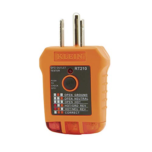
EFFECTIVE GFCI WIRING PROBLEM DETECTION: GFCI Tester detects common wiring problems in standard and GFCI receptacles, ensuring electrical safety