
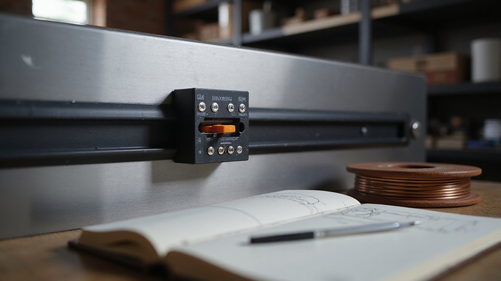

Ever wonder what keeps your control panels organized and easy to manage? That’s where a DIN rail comes in—a simple, standardized metal strip that holds all your modular electrical components in place.
Whether you’re installing circuit breakers or relays, understanding the different profiles and materials helps you choose the best fit for your system.
Keep reading to learn everything you need to know about DIN rails.
What Exactly Is a DIN Rail and Why Does It Exist?
A DIN rail is a standardized metal strip, typically 35 millimeters wide, used inside electrical control panels and enclosures. Its purpose is to serve as a universal mechanical support platform for various modular components. Components such as circuit breakers, terminal blocks, and relays from different manufacturers can be snapped directly onto the rail, eliminating the need for custom brackets and making installation faster and more straightforward. The precise manufacturing of DIN rails ensures consistent alignment, which simplifies wiring layouts and troubleshooting. Some variants feature color coding that helps you quickly identify grounding connections or functional groups. To secure and customize device placement, you’ll use mounting accessories like end stops or rail cutters to trim the length, ensuring a tidy and organized control cabinet. This uniform system transforms a simple metal strip into the backbone of efficient, well-organized electrical control systems. For outdoor power systems, these rails are often paired with MC4 connectors to provide a reliable and standardized interface for solar panel wiring. When pairing DIN rails with a complete power setup, selecting a high-quality inverter for power ensures overall system reliability and stable AC output. For rooftops where aesthetics matter, DIN rails can support equipment that works alongside solar shingles to integrate renewable energy without bulky panel arrays.
The 3 Most Common DIN Rail Profiles You’ll Encounter
The three main DIN rail profiles you’ll encounter are the top hat rail (TS35), the C rail (TS32), and the G rail (G32). The top hat rail (TS35) is the most common in modern panels, measuring 35 mm in width. It offers a range of sizes, including the 7.5 mm version for general use and the 15 mm variant for heavier assemblies. Both adhere to EN 60722 standards, ensuring compatibility across various components and mounting options. These rails are typically made from conductive materials such as copper or aluminum, which efficiently distribute power while providing mechanical support. For enhanced electrical safety, pairing these rails with a whole-house surge protector can safeguard sensitive equipment from voltage spikes. The C rail (TS32) features a 32 mm C-shaped cross-section. While it is an older profile, it remains relevant for legacy installations, particularly when mounting terminals and control components. Its design provides a sturdy, reliable support suited for less modern hardware. The G rail (G32) also measures 32 mm in width but has a deeper recess on one side, distinguishing it from the C rail. Though less common today, it is still used for specific, specialized applications or older equipment. Your choice between these profiles depends on the component fit, cabinet standards, and whether you are maintaining existing installations or planning new setups. For installations requiring reliable connections, top battery picks with terminals ensure consistent performance and safety.

【PREMIUM IN QUALITY】- These slotted DIN rails are made of superb aluminum material, which are very solid and hard to bend, all meet with international EN/IEC and RoHS standards

【PREMIUM IN QUALITY】- These slotted DIN rails are made of superb aluminum material, which are very solid and hard to bend, all meet with international EN/IEC and RoHS standards

Excellent Quality: These slotted DIN rails are made of aluminum, corrosion-resistant, not easily bent, which could be used for a long time.
DIN Rail Materials: Steel vs. Aluminum vs. Alternatives
Steel is the most common material for DIN rails, offering a cost-effective and strong mechanical backbone suitable for many indoor applications. Its zinc plating provides basic rust resistance, making it a practical choice when budget and durability are balanced. However, steel’s weight can be a disadvantage in environments where reducing load is critical or where ease of handling matters. It remains the go-to option for standard panels, but in corrosive or humid settings, upgrading to aluminum or stainless steel may be better suited, as circuit breakers are often mounted on these rails and require reliable structural support. For homeowners relying on sensitive equipment, ensuring a secure mounting system is just as important as selecting the right home battery backup to maintain consistent power during outages. This is particularly true when pairing the rail with a portable power station that provides essential backup energy during grid failures.


What You Will Get: The package contains 12 DIN rail fixed clamp.The size of the DIN rail mounting plate rail fixed clamp is 1.88 x 1.0 inch, offering enough supply for various installment needs. Despite its compact size, it doesn't compromise on performance, a cost-effective set to save your money to buy in packs

How to Choose the Right Size for Your Project
Choose the rail profile that matches your devices’ standards—TS35, TS15, or TS32—before anything else. Most components use 35 mm TS35, but always check the datasheets to be sure. For most general builds, select a 7.5 mm depth; switch to 15 mm if you need to support heavier loads or gain better vibration resistance. Oversizing the depth can waste space and increase costs without benefits.
Next, size the rail length to fit your enclosure’s usable width, leaving space for cable management and wiring bends. Plan your mounting hole spacing, which is typically 25 mm centers for perforated TS35 rails, and verify that your mounting hardware aligns with these measurements. A longer rail provides more flexibility for device spacing and easier access. When selecting the rail, match its rigidity to your most load-heavy component—15 mm deep TS35 rails are suitable for large breakers, while compact terminals work well with TS15 rails. Always ensure the rail’s depth can handle the weight and stress of your devices; improper sizing can lead to flex and reduced reliability. Confirm all measurements and specifications before purchasing to avoid issues during assembly. Connecting the negative cable first can create a dangerous short circuit path, which is why the proper sequence for battery terminals follows the same logic of preventing accidental grounding during installation. However, you should also be aware that overloaded circuits are a common cause of tripping breakers, so avoid exceeding the rail’s rated device current to prevent nuisance trips. To ensure reliable operation, always check that your generator’s pull cord is not damaged before starting, as described in the knowledge base.
Where You’ll Find DIN Rails: From Circuit Breakers to PLCs
DIN rails are a standard mounting solution found in nearly every electrical panel. They support a wide range of components, from miniature circuit breakers and fuse blocks to PLCs and I/O modules. These rails keep components organized and easily accessible, simplifying maintenance and expansion.
In distribution panels, DIN rails hold protection devices like circuit breakers and surge protectors in neat arrays for straightforward servicing. PLCs and their I/O modules snap onto the same rail, facilitating quick additions to your automation system. Terminal blocks are mounted nearby, reducing wiring complexity and keeping connections tidy.
Relays and contactors are also mounted on DIN rails, forming compact switching assemblies that are easier to replace and service. This standardized format is common across industrial control cabinets, process panels, and motor control centers. Color coding on terminal blocks helps you quickly identify different circuits such as signal, power, or ground, increasing safety and reducing wiring errors. Mounting accessories like end brackets and partition plates secure components in place, minimizing clutter and movement within the panel.
How to Install Components on a DIN Rail (Tools and Techniques)
Installing components on a DIN rail involves several precise steps to ensure safe and reliable mounting. Begin by preparing the enclosure: measure the backplate to determine the correct mounting position. Mark the rail’s location carefully to ensure accurate placement. Secure the rail with screws at evenly spaced intervals, making sure it remains level to prevent misalignment of mounted components. To ensure safe power delivery from your generator, always match the cord’s amperage rating to the load requirements.
Cut the DIN rail to the required length using a square-cutting tool, then deburr the edges to remove any sharp burrs that could damage wires or components. Mount the rail onto the enclosure first before attaching any devices. When ready to install components, hook the top edge onto the rail and pivot downward until the spring clip locks securely in place. Slide each component along the rail to its designated position, then install end stops at both ends to prevent movement.
Tighten mounting screws to the recommended torque, typically around 1.3 newton meters, to secure the components without damaging the equipment. Leave sufficient spacing between devices to promote airflow and allow for wiring bends. Always double-check that the spring clips are fully engaged before proceeding. Before energizing the panel, perform electrical integrity checks using a multimeter or insulation tester to confirm correct wiring and secure contacts. For critical backup systems, integrating an automatic transfer switch ensures seamless power transitions during outages. If troubleshooting is needed, a full power cycle can clear many common inverter lockups.

DIN rail 35mm(C45 Rail),15mm adapter.

Generous Quantity: You will receive 10pcs rail mounting brackets, sufficient quantities are available for a wide range of installation scenarios, while at the same time ensuring back-up availability for large projects or maintenance requirements, providing a great user experience

【Precise 35mm DIN Rail Fit】: Engineered for 35mm din rail compatibility, this din rail mount ensures perfect alignment with solid state relays. Achieve superior stability and reliability in electrical installations with precision-designed rail mount components.
DIN Rail Standards: What IEC 60715 and EN 50022 Mean for You
IEC 60715 is the standard that defines the precise dimensions and functional requirements for the 35 mm top-hat rail, commonly known as the TS35 rail. You’ll usually encounter versions like TS35x7.5 or TS35x15, which refer to the rail’s depth in millimeters. Adhering to this standard ensures that terminal blocks, relays, and PLCs from any manufacturer fit securely and interchangeably without fit issues. The standard’s strict manufacturing tolerances mean the rails are consistent in size and shape, enabling cross-brand compatibility. While the base dimensions remain unchanged, it’s worth noting that the rail may have a non-conductive coating, such as paint, which can affect grounding. However, this coating does not alter the core dimensions, so grounding considerations should be checked separately. EN 50022, the older European standard, primarily served as a predecessor but now points to the same geometry governed by IEC 60715. Always verify the rail’s depth because 7.5 mm and 15 mm versions are not interchangeable in practice. This compatibility across brands and standards is the core value of IEC 60715. To maintain reliable electrical connections, regular cleaning of terminals helps prevent corrosion-induced voltage drop, just as with battery cables. For similar reasons, you may need to ensure your breaker box is properly maintained to avoid operational issues. When selecting components for a disconnect switch, fuse compatibility with the rail-mounted terminal blocks is critical to ensure safe and efficient operation.
5 Reasons DIN Rail Became the Global Standard for Control Panels
The main reason DIN rails became the global standard is their standardized compatibility, allowing you to source devices from multiple vendors without being locked into a single brand. This reduces dependency on specific manufacturers and simplifies purchasing decisions. It also makes long-term maintenance easier, as you can replace or add components without concern for compatibility issues. Additionally, the uniform design helps ensure consistent quality and performance across different devices, making the entire control panel more reliable and easier to service. This open architecture mirrors the way solar systems benefit from choosing between microinverter vs optimizer technologies to avoid proprietary lock-in and match specific installation needs.