

Building a DIY power inverter to convert 12V DC into 230V AC might seem tricky, but with the right setup, it’s doable.
You’ll need a center-tapped transformer and a PWM controller like the SG3525 to generate a steady 50 Hz sine wave.
Proper wiring, heatsinking, and testing ensure safe operation and efficiency.
Below, you’ll find all the essential steps to get started.
What Exactly Is a DIY Power Inverter: and How Does It Work?
A DIY power inverter works by converting a battery’s direct current (DC) into alternating current (AC) that resembles household power. This is achieved by creating a circuit that rapidly switches the DC input on and off in a controlled pattern. An oscillator determines the switching frequency, which is usually set to 50 or 60 Hz to match standard mains power.
Power transistors, such as insulated-gate bipolar transistors (IGBTs), amplify the switching signals and control the current flow through a transformer’s primary winding. This switching reverses the current direction continuously, which generates an alternating magnetic field in the transformer. The secondary winding then steps up the voltage to the desired level of AC power. For safety during installation and maintenance, it is a standard practice to disconnect the battery’s negative cable first to prevent accidental short circuits.
The waveform shape crucially depends on how you control the switching pattern. A simple square wave is the easiest to generate but may cause stress on sensitive electronics connected to the inverter. To produce a more sine wave-like output, pulse-width modulation (PWM) is used to better approximate the shape of traditional sinusoidal power. Proper circuit stability is essential; without feedback mechanisms and a clean, steady DC supply, the oscillations can drift, resulting in inconsistent voltage or frequency in the output. Mastering controlled switching is fundamental to building a reliable and efficient inverter. Selecting battery with terminals of high quality, performance, and value is critical for ensuring a stable DC supply to the inverter circuit. A solar charge controller is often used to prevent battery overcharging and deep discharge from the inverter system.
Do You Have These Essential Parts for Your Build?
To build a reliable inverter, you need a set of essential components matched to your desired power and output voltage. Start with a 12V deep-cycle or lead-acid battery, ensuring its capacity can support your intended runtime and load demands. For switching, select low-resistance power MOSFETs such as the IRF3205, paired with a control IC like the SG3525 or TL494. You’ll also need a center-tapped step-up transformer rated for your output voltage, such as 110V or 230V AC. Electrolytic capacitors are necessary for input smoothing, and heat sinks are vital to keep the MOSFETs cool during operation. Use thick-gauge battery cables designed for high current, not just voltage, to prevent overheating and voltage drops. Include a fuse to protect against short circuits and enclose everything in a ventilated metal case to ensure safety and proper heat dissipation.

【Superior Performance】: Lithium iron phosphate battery has high energy density, Long cycle life, Good safety performance, No memory effect, etc. NERMAK LiFePO4 battery has built-in BMS protection to prevent overcharge, Over-discharge, Over-current and short circuit, and very low self-discharge rate. (Not motorcycle starter battery)

Maintenance Free: Manufactured with thick absorbent Glass Mat (AGM) seperators and advanced valve regulated technology, Renogy deep cycle agm batteries save you from acid leakage and frequent maintenance..Batteries Required:no
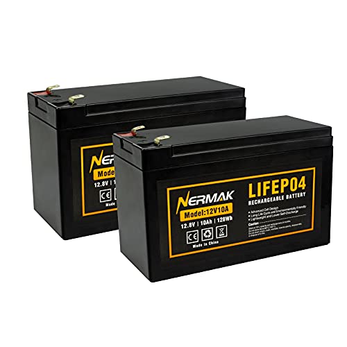
【Superior Performance】: Lithium iron phosphate battery has high energy density, Long cycle life, Good safety performance, No memory effect, etc. NERMAK LiFePO4 battery has built-in BMS protection to prevent overcharge, Over-discharge, Over-current and short circuit, and excessive low self-discharge rate ensuring up to 1-year maintenance-free storage.
Step 1: Build the Oscillator Circuit for Your DIY Inverter
To build the oscillator for your DIY inverter, start with a simple square-wave generator using a CD4047 or a 555 timer. These components are popular for their reliability and ease of use. The oscillator’s stability directly influences your output frequency, so select high-quality, tightly toleranced resistors and capacitors. If you are also considering a home solar backup, compare top roof shingles for integration with your inverter system. Ensure your connection hardware is reliable by using proper MC4 connectors and the recommended crimping tools. Before beginning, review expert reviews for surge protection to safeguard your breaker box during testing.
For the CD4047, set the base frequency near 50 Hz by choosing a 0.01 µF capacitor and a 220 Ω resistor. Fine-tune to 60 Hz by adjusting a 100 kΩ potentiometer in series with the resistor. With a 555 timer, use the formula \(f \approx 1.44 / ((R_1 + 2R_2)C)\) to select resistor and capacitor values for your desired frequency. For example, using R1=10 kΩ, R2=100 kΩ, and a 0.1 µF capacitor yields a tunable frequency range around 50 to 60 Hz.
Keep the oscillator circuit isolated from the high-current switching section to minimize noise coupling. Also, include a buffer stage, such as a transistor or MOSFET switch, to prevent the oscillator from directly driving the power transistors. Proper wiring and component placement ensure stable operation and accurate frequency tuning.
Step 2: Mount Your MOSFETs or Transistors on a Heat Sink
Mount your MOSFETs or transistors on a heat sink by first verifying compatibility. Ensure the heat sink surface is flat within 50 micrometers and free of burrs to guarantee good contact. Apply a thin, even layer of silicone thermal grease or a thermal pad to the device’s base; avoiding excess is crucial as too much grease can reduce performance. Use a mica sheet and plastic washers for electrical isolation if the device’s tab is live. Tighten the mounting screws to the specified torque, tightening evenly across all points to prevent stress and uneven contact. Avoid overcrowding components; vertical fins on the heat sink improve natural convection and heat dissipation. For reliable power backup, it is also essential to consider top solar generators as a complementary solution. If you ever need to service the inverter later, remember that disconnecting battery cables is a critical first safety step before touching any power stage components. After installation, check for electrical isolation with an ohmmeter to confirm there are no shorts between the device tab and the heat sink. For precise verification of these connections, using a digital multimeter can help measure capacitance in related timing circuits. Proper mounting prevents thermal failure and ensures the longevity of your inverter’s power stage.

10 packs complete insulator/mounting kit for TO-3P TO-247 TO-220 Heatsink power semiconductor packages.

Includes 20 pieces black anodized aluminum heatsink 9mm

10 packs complete insulator/mounting kit for TO-3 Heatsink power semiconductor packages.
How to Calculate Battery Ah for Your Desired Runtime (With Formula)
To calculate the battery capacity you need for a specific runtime, start by adding up the average AC load in watts from all devices running at the same time. Multiply that number by your desired number of hours to find watt-hours. Then, divide this watt-hour total by your battery voltage to get the required amp-hours (Ah). It’s important to correct for the depth of discharge (DoD) and inverter efficiency. For lithium batteries, assume about 80% DoD, and for inverter efficiency, around 88%. Choosing between monocrystalline and polycrystalline panels is a separate but related decision when optimizing your solar setup, since your panel type affects how much DC power your inverter receives. For example, if you have a 500-watt load running for 4 hours on a 12-volt system, the calculation is: \( ext{Ah} = rac{500 imes 4}{12 imes 0.80 imes 0.88} \), which equals approximately 237 Ah. Using a conservative DoD helps maximize your battery’s lifespan since deep discharges can shorten charging cycles. Remember to account for idle draw from your inverter, as it also consumes power and slightly reduces your runtime. Always size your battery bank a bit larger than the calculated need to accommodate real-world inefficiencies and ensure reliable operation.

Capacity: total 66.6Wh ( 11.1V 6000mAh, or 3.7V 18000mAh ). Rechargeable DC 12V and 5V USB double output lithium ion battery pack. Voltage range of the 12V output port is 12.6-9V, it is not constant, compatible with most 12 volt devices. 12v DC port: Inner Positive(+), Outer Negative(-).

【12V 25Ah LiFePO4 Battery – The Ultimate AGM/Lead-Acid Replacement】 Ditch bulky lead-acid! ERYY 12V 25AH lithium battery weighs just 6.3lbs (1/3 of lead-acid) and is 50% smaller (7.1"×3"×6.8"), yet delivers 5,000+ cycles (10-year lifespan) with faster charging & zero maintenance. Perfect for solar/off-grid storage, RV/boat power, security equipment system and UPS backup. Upgrade to lighter, smarter, longer-lasting energy – the 12V 25AH LiFePO4 Lithium Batteries outperforms AGM/lead-acid in every way

ML9-12 SLA is a 12V 9AH Sealed Lead Acid (SLA) rechargeable maintenance free battery - UL Certified
Wire the Transformer and Output Stage for Your DIY Inverter
Wiring the transformer and output stage for your DIY inverter requires careful attention to transformer orientation and wiring. Since you’re likely using a step-up transformer in reverse, connect the low-voltage winding as the primary. Use a center-tapped primary to allow the switching stage to alternate current through each half, which helps prevent waveform cancellation.
Connect the MOSFET drains to the transformer primary, their sources to ground, and tie the battery positive to the center tap of the primary winding. Ensure that wiring polarity remains consistent on both halves of the primary to maintain proper phase. For the output, connect the high-voltage winding to your load. To improve waveform quality, especially with pure sine designs, add an LC filter on the secondary side to smooth out voltage fluctuations.
Always heatsink high-current switches to prevent overheating. Use short, heavy-gauge wiring to minimize resistive losses and avoid voltage drops. Before soldering, identify each transformer lead to avoid swapping the primary and secondary. Finally, verify all connections with a test lamp or multimeter before applying full load to safeguard against wiring errors.
Avoid These DIY Inverter Build Mistakes That Blow Components
Ensuring your MOSFETs are appropriately rated is crucial to prevent blowouts. The drain-source voltage rating must exceed the worst-case DC bus transients; otherwise, voltage spikes can puncture the die instantly. For example, if your inverter operates at 400V, select MOSFETs with a voltage rating of at least 600V. When shopping for components, verify that your parts include MC4 connectors for reliable high-current connections. Parallel devices should share current evenly; imbalance causes one leg to overheat and fail prematurely. Matching them properly with consistent gate resistances helps achieve balanced conduction. Keep the gate-drive voltage above 10V to fully turn on the MOSFET, minimizing dissipation. Running the device in its linear region from insufficient gate voltages leads to excessive heat buildup. Adequate thermal management, including heatsinks, fans, or liquid cooling, is essential to dissipate this heat effectively. Also, set dead time sufficiently long—typically a few microseconds—to prevent shoot-through, where both switches conduct simultaneously, shorting the bus. Always include RC snubbers and freewheeling diodes across inductive loads to absorb reverse-EMF spikes. Failing to do so results in high-voltage transients that repeatedly stress switch components. Lastly, never exceed the rated wattage of your inverter. Overloading increases current and heat, rapidly accelerating component failure.

High Voltage Handling: Designed to withstand collector-emitter voltage (VCES) up to 600V, making it ideal for high-voltage power applications.

High Current Dual MOSFET: Dual MOSFET design delivers up to 15 A continuous and 30 A peak at 400 W; strong drive for DC loads; ideal as a dc motor speed controller for robots, pumps, fans

MOSFET Switch Drive Module:for control motor speed light bulbs LED lights DC motors micro-pumps solenoid valves etc
How to Test a New Inverter With a Small Load Safely
Start by performing a thorough safety inspection of the inverter before powering it on. Check all wiring, terminals, and insulation to ensure there are no visible defects and that the DC input voltage matches the rated range specified by the manufacturer. This initial step confirms that the unit is safe to operate and reduces the risk of electrical hazards. Work in a dry, well-ventilated area, wear safety glasses and insulated gloves, and set up meters to monitor voltage, current, and frequency without getting near live conductors. For your first load test, begin with a small resistive load such as a 60-watt bulb. Power the inverter without any load initially, and record the output voltage and frequency, paying attention to any unusual noise, smell, or vibration. Then connect the bulb and observe the output stability and temperature. Gradually increase the load in 100-watt steps, pausing after each to monitor the DC voltage, AC output, and temperature of the inverter. This measured approach allows you to assess efficiency across various load levels and highlight power losses primarily dissipated as heat. Choosing a properly rated solar panel kit can provide a stable DC source for these tests without relying on a battery bank. For example, high-efficiency solar panels typically generate a consistent voltage suitable for input testing. Stop immediately if the protection trips or if excessive heat develops. Verify that overload protection operates correctly, and avoid exceeding the rated capacity unless intentionally testing the protection system. Just as when repairing a breaker box, always confirm the main disconnect is off before handling any high-current connections to prevent arcing or shock.