
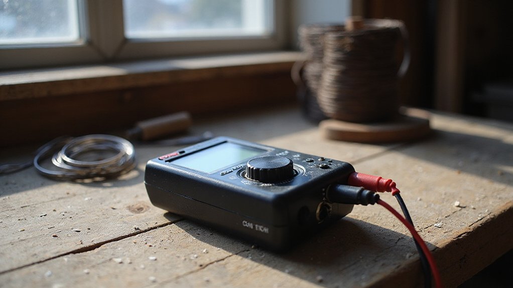

Feeling unsure about how to safely use your Cen-Tech digital multimeter? You’re not alone.
Learning to measure voltage, resistance, and current accurately can seem tricky at first, but with a few simple steps, you’ll be able to get reliable readings without risking harm to yourself or your equipment.
Keep reading, and you’ll have all the essentials to get started confidently.
What’s on Your Cen-Tech Multimeter? A Quick Tour
Before powering up your Cen-Tech multimeter, familiarize yourself with its main components. The large LCD screen at the top displays measurement readings and units clearly, often with a backlit feature or an angled design for easier viewing in different lighting conditions. Use the power button to turn the device on or off, and press the HOLD button to freeze the current reading on display.
The central rotary dial is the control hub, allowing you to select functions such as voltage, resistance, or current. Each setting is clearly marked, making it easy to navigate. When not in use, turning the dial to the OFF position completely powers down the multimeter, conserving battery life. For users who need reliable power for their projects, reviewing top battery picks with terminals can help ensure consistent performance during testing.
Inspect the input jacks at the bottom. The COM jack is your common ground connection, typically used with the black lead. The V/Ω/Hz jack handles measurements for voltage, resistance, and frequency, and is used with the red lead. Always ensure probes are inserted into the correct ports to prevent damage and to ensure safe, accurate measurements. For protecting sensitive electronics from voltage spikes, consider a surge arrester for better performance than a basic lightning arrester. When selecting top surge protectors for a breaker box, expert reviews compare performance to help find the right fit.
Multimeter Safety: 5 Steps Before You Probe Anything
Before connecting your Cen-Tech multimeter to a live circuit, it’s crucial to follow these five safety steps. First, inspect the meter for any damage. Look for cracks, burn marks, or a distorted casing—using damaged equipment increases your risk of shock or incorrect readings. Check the test leads carefully for cuts, fraying, or exposed metal to ensure reliable operation. Your safety gear begins with intact probes and properly shrouded connectors that prevent accidental contact. For tasks like securing probe connections, heat methods without tools offer a safe alternative for insulating exposed wires.
Second, verify that the multimeter’s CAT rating matches your circuit. Using a meter rated for a lower category can lead to dangerous overvoltage exposure. For most household and industrial applications, a CAT III or CAT IV rating is appropriate, depending on the circuit’s voltage and environment. Ensuring correct rating is vital to prevent equipment failure and personal injury. When assessing your home’s electrical demands, consider whether wind generators or solar panels better match your circuit’s power source.
Third, set the meter properly before measurement. Choose the correct function—volts, amps, or resistance—and if your meter has auto-range, select it; otherwise, manually dial to the required range. Insert the black test lead into the common (COM) port first, followed by the red lead into the appropriate port for your measurement type. Double-check that the probes are firmly connected to avoid false readings or sparks.
Fourth, de-energize the circuit whenever possible. Turn off power and disconnect from the power source before making resistance or current measurements. If you must test a live circuit, discharge capacitors first to prevent stored energy from causing shocks. Always ensure the circuit is safe to handle before probing.
Fifth, validate your multimeter’s accuracy by testing it on a known voltage source. This step confirms your instrument is functioning correctly. Keep your fingers behind the safety guards on the test leads and avoid touching metal parts during measurement. Always follow safe practices to protect yourself and ensure precise readings. When verifying accuracy on a battery, understand that charging deep cycle batteries requires correct voltage readings to avoid overcharging and damage.
Measure AC Voltage Safely With Your Cen-Tech Multimeter
To measure AC voltage safely with your Cen-Tech multimeter, start by identifying your test target—wall outlets, lamps, or appliances—so you know what type of circuit you’re working with. Connect the black lead into the COM port and the red lead into the VΩmA port. Turn the dial to the ACV or V~ setting. If you’re unsure of the voltage level, begin with the highest ACV range available, usually 750V or 700V, to prevent overload. If the reading is within a comfortable range, switch to a lower setting for a more precise measurement. For reference, best circuit breakers can be paired with your meter to test live panel voltages safely. Unlike a digital meter, an analog version uses a moving needle and is often preferred for observing rapid fluctuations in voltage. Grounding signal references correctly is important; keep one probe on neutral or ground if possible. When probing, place the probes in parallel across the exposed conductors—polarity doesn’t matter for AC voltage. Hold the probes firmly to avoid slipping, and ensure you’re not touching metal parts beyond the probes. Always remove the negative battery cable first when disconnecting a car battery to prevent accidental shorts. Read the display directly; the RMS value shown is the true effective voltage of the AC signal. If the reading appears low or unstable, switch to a lower range for better clarity. Always stay within the multimeter’s maximum limit, which typically ranges from 600V to 750V AC. Throughout the process, work methodically and with caution to ensure safe and accurate measurements.

7 Function Multimeter


AC voltage measurements up to 750 VAC, 45-450 Hz.
Test DC Voltage on Batteries and Small Electronics
To test DC voltage on batteries and small electronics, set your multimeter to the DCV (direct current voltage) range appropriate for your expected voltage level. Touch the black (negative) probe to the negative terminal or contact point, and the red (positive) probe to the positive terminal or contact. Keep the probes insulated to avoid accidental short circuits or slips across contacts. A stable reading matching the rated supply voltage indicates a healthy power source; a lower or fluctuating reading can reveal weak batteries, low input voltage, or poor contact. If the display shows zero volts, check for dead cells, ensure the probes are making proper contact, and verify you’re on the correct measurement range. Always double-check that your multimeter is set to DCV mode before testing energized circuits to prevent inaccurate readings or potential damage. If the battery is removable, test it as you would a generator without a pull cord by checking its terminals directly for voltage output. For reliable testing results, consider using one of the best check capacitors for digital multimeters when you need to assess capacitor health. Understanding the working principle of a solar generator can help you recognize how stored DC power is later converted for use in your electronics.

Important Tips - This CM2K0R clamp meter can not test DC Current. To measure the AC Current you need to clamp the meter around one of the wires and not the whole power cord. Ensure the conductor to betested is in the center of the clamp head. The clamp Jaw is only used to measure current. Do not measure voltage by clamping the conductor being measured.
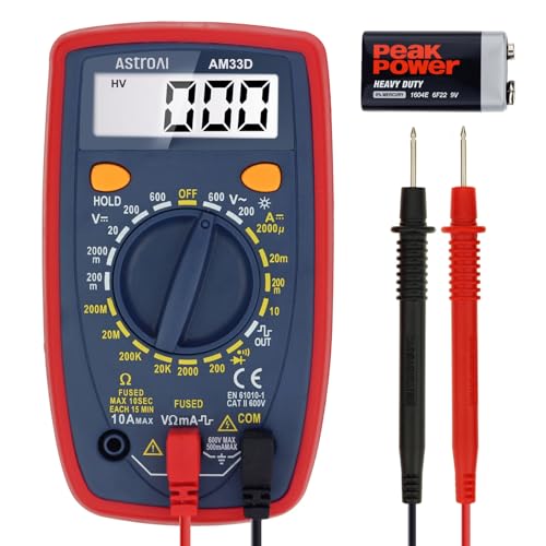
Additional Tips - The following incorrect operations may cause the multimeter not to show results: Firstly, the plugs of test leads are not fully inserted or not inserted into the correct sockets. Secondly, the manual rotary switch is not placed in the correct position. In addition, this meter can not test all AC Current and below 100mV AC Voltage. Please check the user manual carefully before measurement.
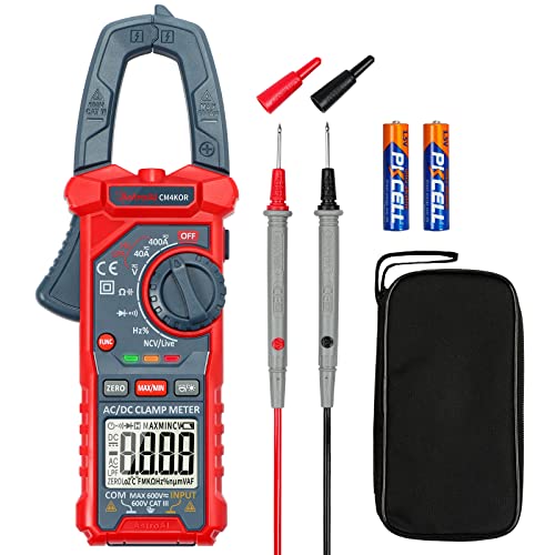
Versatile Digital Clamp Meter: Accurately measures AC/DC Current, AC/DC Voltage, Capacitance, Frequency, Duty Cycle, Resistance, Diode, Continuity and Live Wire Tests. This clamp meter is a really useful tool for solving industrial and household electrical issues.
Test Continuity and Resistance With the Ω and Buzzer
To test continuity and resistance, set your multimeter to the Ω (ohm) setting. Use the 2000k ohm range for checking wires or components. Place one probe on each end of the wire or part you want to test. A reading close to zero ohms indicates a good, continuous connection. If the display shows “OL,” it means the circuit is open or broken. When the resistance drops below approximately 40–50 ohms, the buzzer will sound, signaling a closed path. The low resistance value will also be shown on the screen simultaneously. This quick method helps identify broken wires, blown fuses, or poor solder joints without needing to remove components from the circuit. A clean, low-resistance path is essential for efficient current flow through any conductor, just as busbars require high conductivity to minimize energy loss. For permanent connections like ring terminals, a quality crimping tool ensures a reliable mechanical bond to avoid creating open circuits. An automatic changeover switch uses a similar continuity check to verify a stable primary power source before switching loads.

All-Weather Silicone Flexibility: 40 in modular multimeter test leads / volt meter leads stay supple from deep cold to engine heat
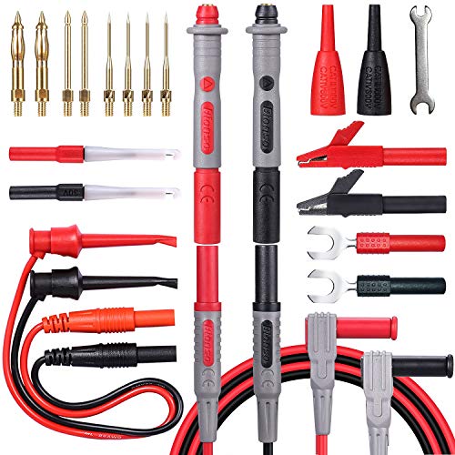
Soft, Safe and Excellent Quality: The upgraded version of the product, the leads are made of high quality silicone, cold and high temperature resistant, very soft, more flexible use. A double insulated lead with 100 high-purity copper wire ensures safety, low resistance and no signal loss. The products are well designed and made.
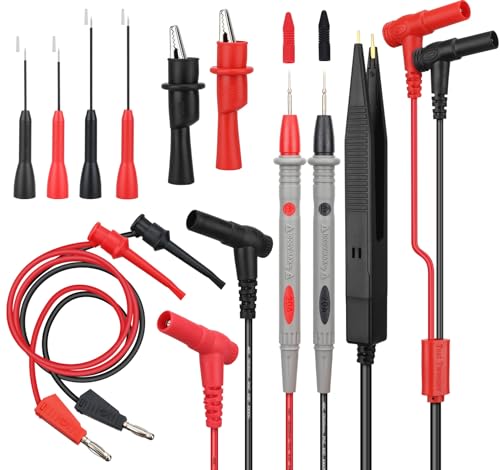
PROFESSIONAL GRADE SAFETY – The SWANLAKE test leads set is CAT III 1000V rated and supports up to 20A, ensuring reliable safety for high-voltage electrical testing with most multimeter and clamp meter brands
Don’t Guess Polarity: Use the Diode Test
To identify a diode’s polarity accurately, avoid guessing based on color or lead length. Instead, use the diode test function on your Cen-Tech meter. Set the meter to the diode symbol and connect the red lead to the VΩmA jack and the black lead to COM. Place the red probe on the suspected anode and the black probe on the cathode. A healthy silicon diode will show a forward voltage between 0.5 and 0.8 volts. Reverse the probes; you should see an open loop (OL), confirming the cathode. If you get a reading in both directions, the diode is shorted and needs replacing. Always power off the circuit and isolate the diode before testing to prevent damage or false readings. Use the band-marked side of the diode along with the meter reading to verify the correct polarity. Never guess—verify with your multimeter for the most reliable results.

Accurately Test Full Features: Accurately measures AC/DC voltage, DC current, resistance, continuity test, diode and batteries.
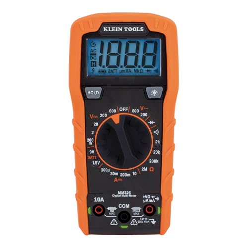
VERSATILE FUNCTIONALITY: Measures AC/DC voltage up to 600V, 10A DC current, 2MΩ resistance; additional features include continuity, diode test and battery test

CAT III 600V Safety Rating: Ensuring your safety when working on electrical systems in common residential and commercial settings
Measure Amps With Your Cen-Tech Multimeter
To measure current with your Cen-Tech multimeter, begin by selecting the correct range and type—set the dial to the DC current function, usually marked with an A and a straight or dashed line. Always start with the highest current range available to avoid damaging the meter if the current is unknown. If your reading is below 0.2 A, switch to the 200 mA range for a more precise measurement. For applications involving larger battery systems, such as LiFePO4 setups, understanding the battery’s current capacity is crucial.
Proper lead placement is essential. Insert the black lead into the COM jack. For high currents, place the red lead into the 10A jack. For lower currents, move the red lead to the VΩmA jack to protect the fuse and achieve better accuracy. Remember, you must connect your meter in series with the circuit—never measure current in parallel. De-energize the circuit first, break the circuit, then connect the meter probes in series. After restoring power, read the display. If the current appears very small, switch to a lower range to get a clear, accurate reading. For context, measuring current in corroded systems can cause inaccurate readings due to increased resistance. For context, selecting a compatible solar converter is critical when measuring current in larger systems like those found in inverter setups.

Important Tips - This CM2K0R clamp meter can not test DC Current. If you have any questions about the product, feel free to contact us! Our California-based support team will respond within 24 hours.
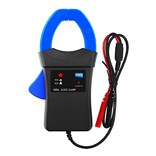
【AC/DC 600A Clamp-on Probe】Capable of measuring AC/DC up to 600 amps, This clamp adapter is built for higher current measurement.

Power circuit measurement and malfunction analysis
Faulty Readings? 5 Quick Fixes for Your Multimeter
If you’re having trouble getting a stable reading from your Cen-Tech multimeter, start by checking a few common issues. First, ensure your dial is set correctly for what you’re measuring—whether that’s DC volts, resistance, or continuity—and confirm that the probes are in the proper jacks. If the display shows irregularities, turn the meter off, then back on to reset any temporary glitches.
A low-battery indicator can cause erratic readings, so replace the batteries immediately if you notice it. Inspect the test leads for cuts, cracks, or loose connections, and reseat them fully into the ports. Dirty tips or oxidation can also affect measurements—clean the probes with a soft cloth or alcohol-based cleaner. For intermittent or inconsistent readings, try swapping to a different set of probes.
Check the fuses if your continuity or resistance readings suddenly stop working—replace any that are blown with the exact same rating. Keep your multimeter within its recommended operating temperature range to avoid unstable measurements. When testing non-conductive materials, switch to resistance mode and allow the reading to settle before recording it. Finally, test your multimeter against a known good source to determine if the issue lies with the meter itself, and recalibrate if necessary. For a similar clean finish on your test leads, use flush cutters to trim any frayed wire ends neatly. Gel batteries, for instance, require specific charging parameters to avoid damage and maintain accuracy during electrical testing.