

Ever wonder how you can see exactly what’s happening inside your home energy system without guesswork?
A CAN bus data logger records every message between your battery, inverter, and meter in real time.
It turns complex data into understandable info.
By understanding this raw data, you can detect issues early and optimize your setup easily.
Keep reading to find out how this device works and how to choose the right one for your needs.
Why Your Home Energy System Needs a CAN Bus Data Logger
Logging all CAN messages directly at the source provides an effective form of system redundancy. Instead of polling individual devices, you capture all communication during normal operation, upholds device states before, during, and after failures, and allows for faster diagnosis. This comprehensive approach preserves a detailed, time-synchronized record that remains intact even if a device such as the inverter or BMS experiences a fault or memory loss. As a result, you eliminate guesswork, rely on precise event data, and can respond swiftly to issues with confidence. This is especially useful when paired with a DIY battery strap that has safety limits for home-made setups. For accurate power analysis, a true power meter is essential to measure actual energy consumption in your circuit, matching the data logger’s precision. For long-term reliability, you should also choose components with battery terminals that offer superior conductivity and a secure connection.
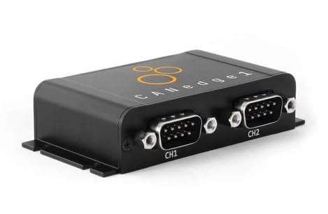
PLUG & PLAY - configure in 2 mins, then connect & forget (<1W power usage)

Dual Channel CAN Interface. Two independent high-speed CAN channels allow simultaneous monitoring, testing, or bridging between networks. Supports CAN 2.0A/B, standard and extended frames, data and remote frames.

Designed for long-term monitoring of pH in aquatic systems
How CAN Bus Logging Captures Raw Data From Batteries and Inverters
Capturing the entire communication stream at the physical bus level yields the raw data needed for comprehensive analysis. You connect a logger directly across the same two-wire CAN bus used by your battery management system and inverter. This passive setup allows the logger to monitor every transmitted and received frame without interference. Since CAN uses a bus topology, it guarantees capturing both request frames sent by devices and subsequent reply frames, enabling reconstruction of the full request-response cycle. Properly securing the wire connections with a 4-way crimping tool ensures a reliable physical tap onto the bus for consistent data capture. While a multimeter can measure voltage or resistance at a single point, it cannot log the high-speed, packetized data stream that a dedicated logger captures on the CAN bus.
Standard CAN frames carry up to eight data bytes, which the logger records in hexadecimal form before any decoding or conversion. Signal interference can corrupt some frames; however, CAN’s built-in Cyclic Redundancy Check (CRC) protection and arbitration field prioritization help ensure data integrity. Frames with lower identifier values often represent critical fault conditions, gaining bus access during contention. Each frame’s data payload encodes values such as decivolts or scaled temperatures, requiring interpretation to derive meaningful units. Multiple frames are typically necessary to compile a complete picture of a battery pack’s status, making comprehensive logging essential for detailed system analysis. A DIY solar panel guide similarly covers materials and wiring layouts for capturing energy data at the system level.
Key Data Points a CAN Bus Data Logger Captures From Batteries, Inverters, and Meters
A CAN bus data logger captures comprehensive data points that reveal the operational state of your battery, inverter, and meter systems. For batteries, it records pack voltage, current, and state of charge, allowing you to monitor overall health and performance. Cell-level metrics such as minimum and maximum voltages help with balancing analysis and ensuring individual cell health. Temperature data, including the lowest and highest cell temperatures, helps track thermal trends and identify hotspots or cooling needs. The logger also exposes charge and discharge limits and flags for protection, like overvoltage or overcurrent events, enabling swift corrective actions. Just as cable ties became an everyday essential by securing and organizing wiring, this data logger securely organizes your system’s operational data into a reliable log. This principle mirrors how a solar generator converts and stores energy by regulating input from solar panels to maintain stable system performance. For even greater integration of renewable energy, consider how high-quality roof shingles with embedded solar panels can streamline your home’s energy generation while maintaining structural integrity.
For inverters and meters, the data logger records AC voltage, frequency, active power, and cumulative energy import and export values. These measurements inform you of system efficiency and energy flow. All these points feed into your data analysis, empowering you to detect inefficiencies, verify system limits, or identify potential faults early. This detailed log of operational parameters ensures you have precise, real-time insights into every subsystem, reducing guesswork and improving system reliability.

Powerful Output: Two AC output ports provide 400 watt continuous output or 800 watt high peak surge when connected to your vehicle’s battery LCD Screen: Screen displays the...
How to Decode Raw CAN Logs Using DBC Files and PC Software
To decode raw CAN logs using DBC files and PC software, load your log file into programs like SavvyCAN or asammdf. Then, import the correct DBC file that matches your CAN network; this file specifies how each message ID maps to physical signals. The DBC details the start bit, signal length, scaling factor, and offset for each parameter. After importing both files, run the decode function in the software. It extracts the raw bits, applies the scaling and offset, and converts the data into understandable physical values like voltage or current. To ensure your decoding setup matches real-world performance, compare top picks for data logging hardware reviewed on sites like Top Power Inverters. This process is similar to how a solar charge controller uses PWM or MPPT technology to regulate energy flow and convert raw electrical input into usable battery charging parameters. If your solar panel system requires precise monitoring, selecting a kit with a built-in display can simplify verifying decoded data against actual output. When dealing with multiplexed signals, ensure your parser correctly identifies and processes the multiplexing bits. Improper handling of multiplexed messages can lead to incorrect readings. Always cross-verify your decoded data with test plots or known values to confirm accuracy.
Choosing a CAN Bus Data Logger for Home Energy: Voltage, Temp, and Storage
To choose a CAN bus data logger for home energy monitoring, ensure its power input matches your site’s supply voltage. Most models operate between 7 V and 36 V DC, but some compact units work within narrower ranges like 8 V to 16 V DC. Reverse-voltage protection is important to prevent damage during incorrect wiring, and a switch-on threshold around 9 V is ideal for battery-backed power rails. For bench testing, USB-powered loggers offer a straightforward solution without needing external power supplies. For safety, always check if your breaker box is hot, as overheating components can indicate faulty wiring or overloaded circuits that could damage sensitive logging equipment. Always begin by tightening cable ties securely to avoid loose connections that may cause intermittent power issues. When connecting the logger to your battery-backed system, always disconnect the negative battery cables first to reduce the risk of short circuits.
Next, verify the temperature rating aligns with your environment. Indoor utility rooms typically stay within -20 °C to +70 °C, but if you plan to monitor unconditioned or outdoor spaces, choose rugged models rated from -40 °C to +85 °C. Storage temperature ratings are also crucial—long-term data integrity depends on the logger’s ability to withstand temperature extremes beyond its operating range.
Finally, confirm the logger provides adequate data storage. Use SD or SDHC cards ranging from 4 GB to 32 GB to accommodate high message volume recordings. Larger capacity cards prevent data loss during extended continuous logging sessions. Wireless data loggers are available but introduce additional complexity; for most home energy projects, wired or removable-media options tend to be simpler and more reliable.
Real-World Benefits of CAN Bus Data Logging: Troubleshooting, Battery Health, and Integration
CAN bus data logging offers essential insights for troubleshooting, monitoring battery health, and system integration. It allows you to detect raw faults such as missing frames or corrupt signals that may be hidden within a dashboard. For example, wiring issues like reversed CAN_H and CAN_L lines or poor termination can be diagnosed instantly by analyzing the raw data. Continuous logging creates detailed records that help you match specific error codes from the Battery Management System (BMS) to exact timestamps, making it easier to distinguish between device faults and bus-wide problems. When selecting components, consider top solar panel picks that feature robust communication interfaces for reliable data logging. When tracking battery health, logging voltage, current, and temperature across multiple charge and discharge cycles reveals early signs of degradation. You can identify abnormal voltage drift or capacity loss before they become critical issues. Integration with inverters and gateways becomes more straightforward because CAN logs verify that charge limits are maintained correctly and that error codes are accurately interpreted. To ensure the logging hardware itself receives clean power and data, applying secure solar connections with proper crimping techniques prevents intermittent signal loss during monitoring. For a stable system, using a reliable grounding wire with proper termination is essential to prevent ground loops and ensure accurate signal integrity.
Wireless connectivity enhances the system by allowing remote data retrieval without physical access, while encrypted transmission ensures your logged data remains secure during transfer. This combination of features provides a comprehensive approach to maintaining, troubleshooting, and optimizing your home energy system.

MCP2515 TJA1050 CAN Bus Module: It consists of MCP2515 and TJA1050 chips, which is convenient for Can Bus Controller and Receiver functions at the same time

Super material: It is made of electronic accessories, nickel plating on surface(anti-oxidatioan), inner conductor: pure copper.it is long lasting and durable for you to use.

【Wide Compatibility】This USB CAN converter seamlessly connects to Raspberry Pi 5/4/Pi3B+/Pi3/Pi Zero(W) and other single-board computers like Jetson Nano and Tinker Board, as well as Windows, Linux, and MacOS laptops for versatile CAN bus integration.